UPPER CONTROL ARM
- DESCRIPTION - UPPER SUSPENSION ARM, BUSHINGS, AND BALL JOINT
- OPERATION - UPPER SUSPENSION ARM, BUSHINGS, AND BALL JOINT
- REMOVAL
- INSTALLATION
DESCRIPTION - UPPER SUSPENSION ARM, BUSHINGS, AND BALL JOINT
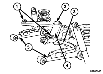
OPERATION - UPPER SUSPENSION ARM, BUSHINGS, AND BALL JOINT
The upper suspension arm (4) provides fore/aft and lateral location of the rear axle. The suspension arm travel is limited through the use of jounce bumpers in compression and shock absorbers in rebound.
REMOVAL
1. Raise and support the vehicle.
2. Support the rear axle with a hydraulic jack.
3. Remove the ball joint pinch bolt from the top of the differential housing bracket .
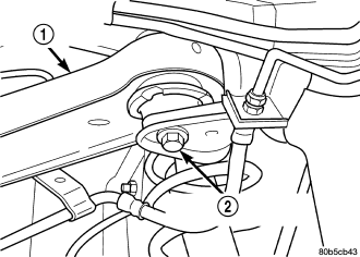
4. Remove partial nuts from the heat shield in order to lower the shield down enough to get the proper clearance to remove the right side bolt (2) from the body.
5. Remove the upper suspension arm mounting bolts (2) from the body and remove the arm (1).
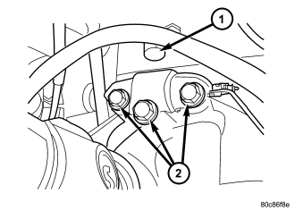
6. Remove the support bracket mounting bolts (2) if needed.
INSTALLATION
1. Position the upper suspension arm (1) in the frame rail brackets .
2. Install the mounting bolts (2) and tighten to 100 N·m (74 ft. lbs.).
3. Retighten the heat shield back into place.
4. Install the support bracket and bolts (2) to the rear differential (if removed).
5. Pull the arm down on the differential housing bracket inserting the ball joint (1) into the support bracket (2) and install the pinch bolt and nut. Tighten the nut to 95 N·m (70 ft. lbs.) .
6. Remove the supports and lower the vehicle.