CLOCKSPRING
DESCRIPTION
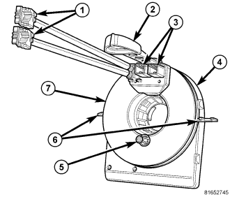
The clockspring assembly is secured with two plastic latches integral to the back of the case onto the upper steering column housing near the top of the steering column behind the steering wheel. Two additional mounting tabs (6) with slotted holes integral to the sides of the case are secured by two screws that secure the upper and lower steering column shrouds to the column housing and to each other. On vehicles equipped with an optional Electronic Stability Program (ESP), the clockspring also includes an integral, internal Steering Angle Sensor (SAS) that is serviced as a unit with the clockspring.
The clockspring consists of a flat, round molded plastic case (4) with a stubby tail that hangs below the steering column. Within the plastic case is a spool-like molded plastic rotor with a large exposed hub. The upper surface of the rotor hub has a large center hole, an engagement dowel (5), two short pigtail wires with connectors (1), and two connector receptacles (3) that face toward the steering wheel.
Service replacement clocksprings are shipped pre-centered and with a molded plastic locking pin (2) that snaps into a receptacle on the rotor and is engaged with tabs on the upper surface of the clockspring case. The locking pin secures the centered clockspring rotor to the clockspring case during shipment and handling, but must be removed from the clockspring after it is installed on the steering column. (Refer to 8 - ELECTRICAL/RESTRAINTS/CLOCKSPRING - STANDARD PROCEDURE - CLOCKSPRING CENTERING).
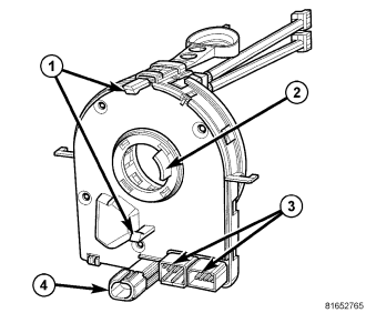
Besides the two latch features (1), the lower surface of the case facing toward the instrument panel includes two integral connector receptacles (3). On units with the SAS there is an additional applied connector (4) with a short pigtail wire on the lower surface of the case, inboard of the two integral connectors. The lower surface of the rotor hub has a molded plastic turn signal cancel cam with a single lobe (2) that is integral to the rotor.
Within the plastic case and wound around the rotor spool is a long ribbon-like tape that consists of several thin copper wire leads sandwiched between two thin plastic membranes. The outer end of the tape terminates at the connector receptacles that face the instrument panel, while the inner end of the tape terminates at the pigtail wires and connector receptacles that face the steering wheel.
The clockspring cannot be repaired. If the clockspring is ineffective, damaged, or if the driver airbag has been deployed, the clockspring must be replaced.
OPERATION
The clockspring is a mechanical electrical circuit component that is used to provide continuous electrical continuity between the fixed instrument panel wire harness and the electrical components mounted on or in the rotating steering wheel. On this vehicle the rotating electrical components include the driver airbag, the horn switch, the speed control switches, and the remote radio switches, if the vehicle is so equipped. The clockspring case is positioned and secured to the upper steering column housing near the top of the steering column. The connector receptacles on the tail of the fixed clockspring case connect the clockspring to the vehicle electrical system through two take outs with connectors from the instrument panel wire harness.
The clockspring rotor is movable and is keyed by the engagement dowel that is molded onto the upper surface of the rotor hub to an opening that is cast into the steering wheel armature. The lobe of the turn signal cancel cam on the lower surface of the clockspring rotor hub contacts a turn signal cancel actuator of the multi-function switch to provide automatic turn signal cancellation. On units with an integral, internal Steering Angle Sensor (SAS), a connector and pigtail wire on the lower clockspring case connects the sensor to the vehicle electrical system through a third dedicated take out and connector of the instrument panel wire harness.
The yellow-sleeved pigtail wires on the upper surface of the clockspring rotor connect the clockspring to the multistage driver airbag, while a steering wheel wire harness connects the connector receptacle on the upper surface of the clockspring rotor to the horn switch and, if the vehicle is so equipped, to the optional speed control switches and remote radio switches on the steering wheel.
Like the clockspring in a timepiece, the clockspring tape has travel limits and can be damaged by being wound too tightly during full stop-to-stop steering wheel rotation. To prevent this from occurring, the clockspring is centered when it is installed on the steering column. Centering the clockspring indexes the clockspring tape to the movable steering components so that the tape can operate within its designed travel limits. However, if the clockspring is removed from the steering column or if the steering shaft is disconnected from the steering gear, the clockspring spool can change position relative to the other steering components. The clockspring must be re-centered following completion of this service or the tape may be damaged.
Service replacement clocksprings are shipped pre-centered and with a locking pin installed. This locking pin should not be removed until the clockspring has been installed on the steering column. If the locking pin is removed before the clockspring is installed on a steering column, the clockspring centering procedure must be performed. (Refer to 8 - ELECTRICAL/RESTRAINTS/CLOCKSPRING - STANDARD PROCEDURE - CLOCKSPRING CENTERING).
The clockspring as well as the hard wired inputs and outputs of the clockspring may be diagnosed using conventional diagnostic tools and procedures. Refer to the appropriate wiring information. However, conventional diagnostic methods will not prove conclusive in the diagnosis of the SAS or the electronic controls or communication between other modules and devices that provide features of the ESP. The most reliable, efficient, and accurate means to diagnose the SAS or the electronic controls and communication related to SAS operation requires the use of a diagnostic scan tool. Refer to the appropriate diagnostic information.
REMOVAL
WARNING: To avoid personal injury or death, on vehicles equipped with airbags, disable the supplemental restraint system before attempting any steering wheel, steering column, airbag, occupant classification system, seat belt tensioner, impact sensor, or instrument panel component diagnosis or service. Disconnect and isolate the battery negative (ground) cable, then wait two minutes for the system capacitor to discharge before performing further diagnosis or service. This is the only sure way to disable the supplemental restraint system. Failure to take the proper precautions could result in accidental airbag deployment.
CAUTION: A service replacement clockspring is shipped with the clockspring pre-centered and with a molded plastic locking pin installed. This locking pin should not be removed until the clockspring has been installed on the steering column. If the locking pin is removed before the clockspring is installed on a steering column, the clockspring centering procedure must be performed. (Refer to 8 - ELECTRICAL/RESTRAINTS/CLOCKSPRING - STANDARD PROCEDURE - CLOCKSPRING CENTERING).
NOTE: Before starting this procedure, be certain to turn the steering wheel until the front wheels are in the straight-ahead position.
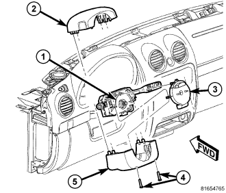
1. Place the front wheels in the straight ahead position.
2. Disconnect and isolate the battery negative cable.
3. Remove the driver airbag from the steering wheel. (Refer to 8 - ELECTRICAL/RESTRAINTS/DRIVER AIRBAG - REMOVAL).
4. Disconnect the steering wheel wire harness connectors from the upper clockspring connector receptacles.
CAUTION: Be certain that the screws that secure the steering wheel puller to the steering wheel are fully engaged in the steering wheel armature without passing through the steering wheel and damaging the clockspring.
5. Remove the steering wheel from the steering column (8). (Refer to 19 - STEERING/COLUMN/STEERING WHEEL - REMOVAL).
6. If the vehicle is equipped with the optional tilt steering column, move the column to the fully lowered position and leave the tilt release lever in the released (down) position.
7. From below the steering column, remove the two screws (4) that secure the lower shroud (5) to the upper shroud (2).
8. Using hand pressure, push gently inward on both sides of the upper shroud above the parting line between the upper and lower shrouds to release the snap features that secure the two shroud halves to each other.
9. Remove both the upper and lower shrouds from the steering column.
10. Disconnect the two instrument panel wire harness connectors for the clockspring from the two connector receptacles located below the steering column on the back of the clockspring (3) case.
11. If the vehicle is equipped with the optional Electronic Stability Program (ESP) there will be an applied pigtail wire connector located below the steering column on the back of the clockspring case for the Steering Angle Sensor (SAS) that is internal to the clockspring. Disconnect the instrument panel wire harness connector for the SAS from the pigtail connector.
12. Using a small thin-bladed screwdriver, release the two integral plastic latches that secure the back of the clockspring case to the steering column lock housing (1).
13. Remove the clockspring from the steering column lock housing. The clockspring cannot be repaired. It must be replaced if ineffective or damaged, or if the driver airbag has been deployed.
14. If the removed clockspring is to be reused, be certain to secure the clockspring rotor to the clockspring case to maintain clockspring centering until it is reinstalled on the steering column. If clockspring centering is not maintained, the clockspring must be centered again before it is reinstalled. (Refer to 8 - ELECTRICAL/RESTRAINTS/CLOCKSPRING - STANDARD PROCEDURE - CLOCKSPRING CENTERING).
INSTALLATION
WARNING: To avoid personal injury or death, on vehicles equipped with airbags, disable the supplemental restraint system before attempting any steering wheel, steering column, airbag, occupant classification system, seat belt tensioner, impact sensor, or instrument panel component diagnosis or service. Disconnect and isolate the battery negative (ground) cable, then wait two minutes for the system capacitor to discharge before performing further diagnosis or service. This is the only sure way to disable the supplemental restraint system. Failure to take the proper precautions could result in accidental airbag deployment.
CAUTION: A service replacement clockspring is shipped with the clockspring pre-centered and with a molded plastic locking pin installed. This locking pin should not be removed until the clockspring has been installed on the steering column. If the locking pin is removed before the clockspring is installed on a steering column, the clockspring centering procedure must be performed. (Refer to 8 - ELECTRICAL/RESTRAINTS/CLOCKSPRING - STANDARD PROCEDURE - CLOCKSPRING CENTERING).
NOTE: Before starting this procedure, be certain to turn the steering wheel until the front wheels are in the straight-ahead position.
1. Carefully slide the centered clockspring (3) down over the steering column upper shaft until the two integral plastic latches on the back of the clockspring case are fully engaged through their openings in the steering column lock housing (1).
2. If the vehicle is equipped with the optional Electronic Stability Program (ESP) there will be an applied pigtail wire connector located below the steering column on the back of the clockspring case for the Steering Angle Sensor (SAS) that is internal to the clockspring. Reconnect the instrument panel wire harness connector for the SAS to the pigtail connector.
3. Reconnect the two instrument panel wire harness connectors for the clockspring to the two connector receptacles located below the steering column on the back of the clockspring case.
4. Position the upper (2) and lower (5) shrouds onto the steering column.
5. Align the snap features on the lower shroud with the receptacles in the upper shroud and apply hand pressure to snap them together.
6. From below the steering column, install and tighten the two screws (4) that secure the lower shroud to the upper shroud. Tighten the screws to 2 N·m (18 in. lbs.).
7. If the vehicle is equipped with the optional tilt steering column, move the column back to the fully raised position and move the tilt release lever back to the locked (up) position.
8. If a new clockspring has been installed, remove the plastic locking pin that secures the clockspring rotor to the clockspring case to maintain clockspring centering.
9. Reinstall the steering wheel onto the steering column. (Refer to 19 - STEERING/COLUMN/STEERING WHEEL - INSTALLATION).
NOTE: Be certain that the steering wheel mounting screw is tightened to the proper torque specification to ensure proper clockspring operation.
10. Reconnect the steering wheel wire harness connector to the upper clockspring connector receptacle.
11. Reinstall the driver airbag onto the steering wheel. (Refer to 8 - ELECTRICAL/RESTRAINTS/DRIVER AIRBAG - INSTALLATION).
12. Reconnect the battery negative cable.