PASSENGER AIRBAG ON/OFF INDICATOR
DESCRIPTION
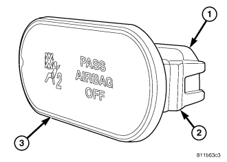
Vehicles equipped with the Occupant Classification System (OCS) include a passenger airbag on/off indicator (3), which is located in the inboard grab handle end cap located on the instrument panel between the passenger airbag door and the glove box. The passenger airbag on/off indicator and the grab handle are present only in vehicles equipped with the OCS. Vehicles without the OCS have only a trim bezel on the instrument panel, instead of a grab handle.
The passenger airbag on/off indicator consists of a molded plastic housing with an integral connector receptacle (1) at the back, an integral latch tab (2) on each side, and an oblong dark translucent outer lens. The opaque words PASS AIRBAG OFF and an opaque International Control and Display Symbol icon for Passenger Airbag Off or Not Available are imprinted on the back of the lens within the indicator. The dark outer lens prevents the indicator text and icon from being clearly visible when it is not illuminated. An amber Light Emitting Diode (LED) behind the lens causes the text and icon to appear silhouetted against an amber field through the translucent lens when the indicator is illuminated from behind by the LED.
The passenger airbag on/off indicator cannot be repaired or adjusted and, if ineffective or damaged, the indicator unit must be replaced.
OPERATION
In vehicles equipped with the Occupant Classification System (OCS), the passenger airbag on/off indicator gives an indication when the passenger airbag and seat belt tensioner deployment circuits are disabled by the Airbag Control Module (ACM) (also known as the Occupant Restraint Controller/ORC). This indicator is controlled by a transistor within the ACM through a hard wired output based upon ACM programming and electronic occupant classification messages received by the ACM over the Programmable Communications Interface (PCI) data bus from the Occupant Classification Module (OCM).
The passenger airbag on/off indicator Light Emitting Diode (LED) is completely controlled by the ACM. The LED receives a battery current input on the fused ignition switch output (run-start) circuit. Therefore, the LED will always be OFF when the ignition switch is in any position except ON or START. The LED only illuminates when it is provided a path to ground by the ACM transistor. The ACM will turn ON the passenger airbag on/off indicator for the following reasons:
- Bulb Test - Each time the ignition switch is turned to the ON position the passenger airbag on/off indicator is illuminated for about six seconds.
- Child Seat Detected (or Load Less Than Minimum Weight Threshold) Occupant Classification Message - Each time the ACM receives an electronic message from the OCM indicating a child seat has been detected in the passenger side front seat (or that the seat load is less than a minimum weight threshold) the passenger airbag and seat belt tensioner deployment circuits are deactivated and the passenger airbag on/off indicator will be illuminated. The indicator remains illuminated until the ACM receives an occupant classification message indicating that the passenger side front seat is empty, that the seat is occupied by a load equal to or greater than a minimum weight threshold, or until the ignition switch is turned to the OFF position, whichever occurs first.
- Load Undetermined Occupant Classification Message - Each time the ACM receives an electronic message from the OCM indicating that a load cannot be determined in the passenger side front seat, the passenger airbag and seat belt tensioner deployment circuits are deactivated and the passenger airbag on/off indicator will be illuminated. The indicator remains illuminated until the ACM receives an occupant classification message indicating that the passenger side front seat is empty, that the seat is occupied by a load equal to or greater than a minimum weight threshold, or until the ignition switch is turned to the OFF position, whichever occurs first.
- Communication Error - If the ACM receives invalid occupant classification messages or no messages from the OCM, the passenger airbag on/off indicator is illuminated. The indicator remains illuminated until the ACM receives a valid message from the OCM indicating that the passenger side front seat is empty, that the seat is occupied by a load equal to or greater than a minimum weight threshold, or until the ignition switch is turned to the OFF position, whichever occurs first.
The ACM continually monitors the occupant classification messages from the OCM to decide whether the passenger airbag and seat belt tensioner deployment circuits should be activated or deactivated. Note that there may be several seconds of delay between changes in the detected occupant status and passenger airbag on/off indications. This is a programmed feature of the OCM used to prevent a flashing indicator condition resulting from the normal shifting of occupant weight on the passenger seat cushion. The ACM then provides the proper control output to turn the passenger airbag on/off indicator ON or OFF.
The ACM will store a Diagnostic Trouble Code (DTC) for any malfunction it detects. The hard wired circuits between the passenger airbag on/off indicator and the ACM may be diagnosed using conventional diagnostic tools and procedures. Refer to the appropriate wiring information. However, conventional diagnostic methods will not prove conclusive in the diagnosis of the passenger airbag on/off indicator or the electronic controls and communication between other modules and devices that provide features of the OCS. The most reliable, efficient, and accurate means to diagnose the passenger airbag on/off indicator or the electronic controls and communication related to passenger airbag on/off indicator operation requires the use of a diagnostic scan tool. Refer to the appropriate diagnostic information.
REMOVAL
WARNING: To avoid personal injury or death, on vehicles equipped with airbags, disable the supplemental restraint system before attempting any steering wheel, steering column, airbag, occupant classification system, seat belt tensioner, impact sensor, or instrument panel component diagnosis or service. Disconnect and isolate the battery negative (ground) cable, then wait two minutes for the system capacitor to discharge before performing further diagnosis or service. This is the only sure way to disable the supplemental restraint system. Failure to take the proper precautions could result in accidental airbag deployment.
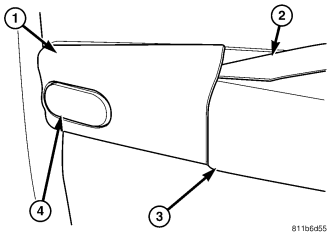
1. Disconnect and isolate the battery negative cable. Wait two minutes for the system capacitor to discharge before further service.
2. Using a trim stick (2) or another suitable wide flat-bladed tool, gently pry the inboard grab handle end cap (1) upwards at the parting line between the cap and the grab handle (3) far enough to disengage the cap from the handle.
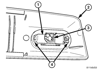
3. Pull the end cap (2) away from the instrument panel far enough to access and disconnect the wire harness connector for the passenger airbag on/off indicator from the connector receptacle (3) on the back of the indicator housing (1).
4. From the back of the inboard end cap, depress the two latches (4) toward the indicator housing and push the indicator out through the face of the end cap.
INSTALLATION
WARNING: To avoid personal injury or death, on vehicles equipped with airbags, disable the supplemental restraint system before attempting any steering wheel, steering column, airbag, occupant classification system, seat belt tensioner, impact sensor, or instrument panel component diagnosis or service. Disconnect and isolate the battery negative (ground) cable, then wait two minutes for the system capacitor to discharge before performing further diagnosis or service. This is the only sure way to disable the supplemental restraint system. Failure to take the proper precautions could result in accidental airbag deployment.
1. From the face of the inboard end cap (2), align the passenger airbag on/off indicator housing (1) with the mounting hole.
2. Using hand pressure, push the indicator firmly and evenly into inboard end cap until the two latches (4) are fully engaged on the back of the cap.
3. Position the indicator and end cap unit close enough to the instrument panel to reconnect the wire harness connector for the indicator to the indicator connector receptacle (3). Be certain that the connector is fully engaged in the receptacle.
4. Align the indicator and end cap unit with the inboard end of the grab handle, and engage the lower snap feature of the end cap to the bottom of the grab handle.
5. Using hand pressure, push the upper edge of the end cap firmly and evenly over the top of the grab handle until the cap snaps into place.
6. Do not reconnect the battery negative cable at this time. The supplemental restraint system verification test procedure should be performed following service of any supplemental restraint system component. (Refer to 8 - ELECTRICAL/RESTRAINTS - STANDARD PROCEDURE - VERIFICATION TEST).
7. Following successful completion of the supplemental restraint system verification test procedure, perform the Occupant Classification System Verification Test using a diagnostic scan tool. Refer to the appropriate diagnostic procedures.