SEAT BELT SWITCH
DESCRIPTION
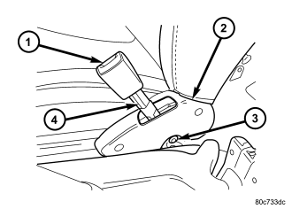
The seat belt switches for this vehicle are actually Hall Effect-type sensors. This sensor consists of a fixed-position, Hall Effect Integrated Circuit (IC) chip and a small permanent magnet that are integral to the driver side and passenger side front seat belt buckle (1). The front seat belt buckles are located on stamped steel stanchions and secured with a screw (3) to the inboard side of each front seat cushion frame between the seat and the floor panel transmission tunnel.
The seat belt switches are connected to the vehicle electrical system through a two-lead pigtail wire (4) and connector on the front seat belt buckle-half, which is connected to a wire harness connector and take out of the seat wire harness beneath the rear edge of each front seat cushion frame. A radio noise suppression capacitor is connected in parallel with the IC where the two pigtail wire leads connect to the IC pins.
The seat belt switches cannot be adjusted or repaired and, if ineffective or damaged, the entire front seat belt buckle-half unit must be replaced.
OPERATION
The seat belt switches are designed to provide a status signal to the seat belt switch sense inputs of the ElectroMechanical Instrument Cluster (EMIC) indicating whether the driver side and passenger side front seat belts are fastened. The EMIC uses these inputs to control the seat belt indicator based upon the status of the driver side and passenger side front seat belt switches.
A spring-loaded plastic slide with a small, enclosed permanent magnet is integral to the buckle latch mechanism. When a seat belt tip-half is inserted and latched into the seat belt buckle, the slide is pushed downward and into close proximity of the Hall Effect Integrated Circuit (IC) chip within the buckle. The field of the permanent magnet induces a current within the chip. The chip provides this induced current as an output to the EMIC, which monitors the current to determine the status of the front seat belts. When the seat belt is unbuckled, the spring-loaded slide and permanent magnet move upward and away from the IC, causing the output current from the seat belt switch to be reduced.
The seat belt switch receives a supply of current from the EMIC, and the EMIC senses the status of the front seat belt through its pigtail wire connection to the seat wire harness. The EMIC also monitors the condition of the seat belt switch circuit and will store a Diagnostic Trouble Code (DTC) for any fault that is detected in the seat belt switch circuit.
The hard wired circuits between the seat belt switches and the EMIC may be diagnosed using conventional diagnostic tools and procedures. Refer to the appropriate wiring information. However, conventional diagnostic methods will not prove conclusive in the diagnosis of the switches or the electronic controls or communication between other modules and devices that provide features of the supplemental restraint system. The most reliable, efficient, and accurate means to diagnose the seat belt switches or the electronic controls and communication related to seat belt switch operation requires the use of a diagnostic scan tool. Refer to the appropriate diagnostic information.