STANDARD PROCEDURE
TIRE ROTATION
Tires on the front and rear operate at different loads and perform different steering, driving, and braking functions. For these reasons they wear at unequal rates and tend to develop irregular wear patterns. These effects can be reduced by rotating the tires at regular intervals. The benefits of tire rotation are:
- Increase tread life
- Maintain traction levels
- A smooth, quiet ride
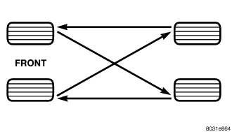
The suggested method of tire rotation is . Other rotation methods can be used, but they will not provide all the tire longevity benefits.
MATCH MOUNTING
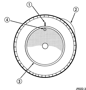
Tires and wheels are currently match mounted at the factory. Match mounting is a technique used to reduce runout in the wheel/tire assembly. This means that the high spot of the tire is aligned with the low spot on the wheel rim. The high spot on the tire is marked with a paint mark or a bright colored adhesive label on the outboard sidewall. The low spot on the rim is identified with a label on the outside of the rim and a dot on the inside of the rim. If the outside label has been removed the tire will have to be removed to locate the dot on the inside of the rim.
Before dismounting a tire from its wheel, a reference mark should be placed on the tire at the valve stem location. This reference will ensure that it is remounted in the original position on the wheel.
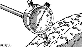
1. Use a dial indicator to locate the high spot of the tire on the center tread rib . Record the indicator reading and mark the high spot on the tire. Place a mark on the tire at the valve stem location .
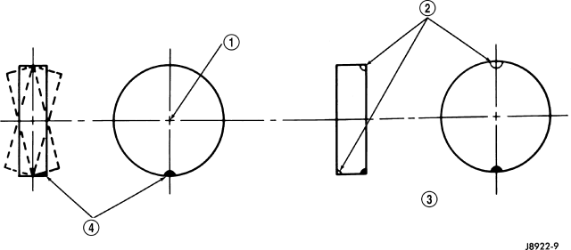
2. Break down the tire and remount it 180 degrees on the rim .
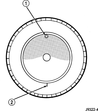
3. Measure the total runout again and mark the tire to indicate the high spot.
4. If runout is still excessive use the following procedures.
a. If the high spot is within 101.6 mm (4.0 in.) of the first spot and is still excessive, replace the tire.
b. If the high spot is within 101.6 mm (4.0 in.) of the first spot on the wheel, the wheel may be out of specifications, (Refer to 22 - TIRES/WHEELS - DIAGNOSIS AND TESTING).
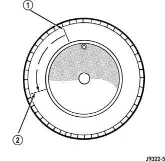
c. If the high spot is NOT within 101.6 mm (4.0 in.) of either high spot, draw an arrow on the tread from second high spot to first. Break down the tire and remount it 90 degrees on rim in that direction . This procedure will normally reduce the runout to an acceptable amount.
WHEEL BALANCING
It is recommended that a two plane service dynamic balancer be used when a tire and wheel assembly require balancing. Refer to balancer operation instructions for proper cone mounting procedures. Typically use front cone mounting method for steel wheels. For aluminum wheel use back cone mounting method without cone spring.
NOTE: Static should be used only when a two plane balancer is not available.
NOTE: Cast aluminum and forged aluminum wheels require coated balance weights and special alignment equipment.
Wheel balancing can be accomplished with either on or off vehicle equipment. When using on-vehicle balancing equipment, remove the opposite wheel/tire. Off-vehicle balancing is recommended.
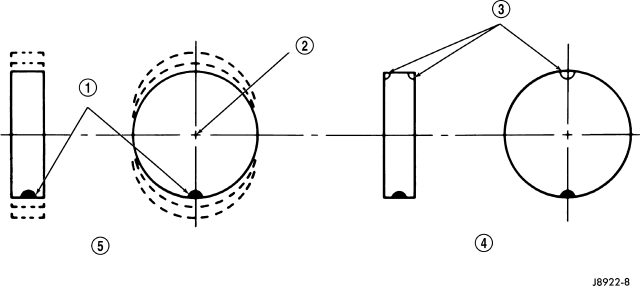
For static balancing, find location of heavy spot causing the imbalance. Counter balance wheel directly opposite the heavy spot. Determine weight required to counter balance the area of imbalance. Place half of this weight on the inner rim flange and the other half on the outer rim flange .
For dynamic balancing, the balancing equipment is designed to locate the amount of weight to be applied to both the inner and outer rim flange .