SENTRY KEY REMOTE ENTRY MODULE
DESCRIPTION
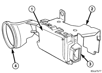
The Sentry Key REmote Entry Module (SKREEM) (1) is sometimes referred to as the Wireless Control Module (WCM). The SKREEM is the primary component of the Sentry Key Immobilizer System (SKIS). It is also the receiver for the Remote Keyless Entry (RKE) system and the Tire Pressure Monitor (TPM) system. The SKREEM is located on the right side of the steering column, near the ignition lock cylinder housing and is concealed beneath the steering column shrouds. The molded black plastic housing for the SKREEM has an integral molded plastic halo-like antenna ring (4) that extends from one end. When the SKREEM is properly installed, the antenna ring is oriented around the circumference of the ignition lock cylinder housing.
A single integral connector receptacle (3) is located on the opposite end of the SKREEM housing from the antenna ring. A stamped metal mounting bracket (2) secured to the SKREEM housing is used to secure the component to the right lower flange of the steering column jacket. The SKREEM is connected to the vehicle electrical system through a single take out and connector of the instrument panel wire harness.
Several SKREEM modules are used, specific to optional vehicle equipment and the market in which the vehicle is sold. The SKREEM cannot be adjusted or repaired. If ineffective or damaged, the entire SKREEM unit must be replaced.
OPERATION
The Sentry Key REmote Entry Module (SKREEM) (also known as the Wireless Control Module/WCM) contains a Radio Frequency (RF) transceiver and a microprocessor. The SKREEM transmits RF signals to, and receives RF signals from the Sentry Key transponder through a tuned antenna enclosed within the molded plastic antenna ring integral to the SKREEM housing. If this antenna ring is not mounted properly around the ignition lock cylinder housing, communication problems between the SKREEM and the transponder may arise. These communication problems will result in Sentry Key transponder-related faults.
The SKREEM also serves as the Remote Keyless Entry (RKE) RF receiver and, if the vehicle is so equipped, the receiver for the Tire Pressure Monitor (TPM) system. (Refer to 8 - ELECTRICAL/POWER LOCKS - DESCRIPTION) or (Refer to 22 - TIRES/WHEELS/TIRE PRESSURE MONITORING - DESCRIPTION). The SKREEM communicates over the Programmable Communications Interface (PCI) data bus with the Body Control Module (BCM), the Electronic Vehicle Information Center (EVIC), the Powertrain Control Module (PCM) or the diagnostic scan tool.
The SKREEM and the PCM both use software that includes a rolling code algorithm strategy, which helps to reduce the possibility of unauthorized Sentry Key Immobilizer System (SKIS) disarming. The rolling code algorithm ensures security by preventing an override of the SKIS through the unauthorized substitution of the SKREEM or the PCM. However, the use of this strategy also means that replacement of either the SKREEM or the PCM units will require a system initialization procedure to restore system operation.
The SKREEM retains in memory the ID numbers of any Sentry Key transponder that is programmed into it. A maximum of eight Sentry Key transponders can be programmed into the SKREEM. For added system security, each SKREEM is programmed with a unique Secret Key code. This code is stored in memory, sent over the PCI data bus to the PCM, and is encoded to the transponder of every Sentry Key that is programmed into the SKREEM. Therefore, the Secret Key code is a common element that is found in every component of the Sentry Key Immobilizer System (SKIS).
Another security code, called a PIN, is used to gain access to the SKREEM Secured Access Mode. The Secured Access Mode is required during service to perform the SKIS initialization and Sentry Key transponder programming procedures. The SKREEM also stores the Vehicle Identification Number (VIN) in its memory, which it learns through a PCI data bus message from the PCM during SKIS initialization.
In the event that a SKREEM replacement is required, the Secret Key code can be transferred to the new SKREEM from the PCM using the diagnostic scan tool and the SKIS initialization procedure. Proper completion of the SKIS initialization will allow the existing Sentry Keys to be programmed into the new SKREEM so that new keys will not be required. In the event that the original Secret Key code cannot be recovered, SKREEM replacement will also require new Sentry Keys. The diagnostic scan tool will alert the technician during the SKIS initialization procedure if new Sentry Keys are required.
When the ignition switch is turned to the ON position, the SKREEM transmits an RF signal to excite the transponder in the ignition key. The SKREEM then waits for an RF signal response from the transponder. If the response received identifies the key as valid, the SKREEM sends an electronic valid key message to the PCM over the PCI data bus. If the response received identifies the key as invalid or if no response is received from the key transponder, the SKREEM sends an invalid key message to the PCM. The PCM will enable or disable engine operation based upon the status of the SKREEM messages. It is important to note that the default condition in the PCM is an invalid key; therefore, if no message is received from the SKREEM by the PCM, the engine will be disabled and the vehicle immobilized after two seconds of running.
The SKREEM also sends electronic security indicator request messages to the BCM over the PCI data bus to tell the BCM how to operate the security indicator in the ElectroMechanical Instrument Cluster (EMIC). The security indicator request message tells the BCM to turn the indicator ON for about three seconds each time the ignition switch is turned to the ON position as a bulb test. After completion of the bulb test, the SKREEM sends security indicator request messages to the BCM to turn the indicator OFF, turn the indicator ON, or to flash the indicator ON and OFF. If the security indicator flashes upon ignition ON or stays ON solid after the bulb test, it signifies a SKIS fault.
If the SKREEM detects a system malfunction or if the SKIS has become ineffective, the security indicator will stay ON solid. If the SKREEM detects an invalid key or if a key transponder-related fault exists, the security indicator will flash. If the vehicle is equipped with the Customer Learn transponder programming feature, the SKREEM will also send messages to the BCM to flash the security indicator and to generate a single audible chime whenever the Customer Learn programming mode is being utilized. (Refer to 8 - ELECTRICAL/VEHICLE THEFT SECURITY - STANDARD PROCEDURE - SENTRY KEY TRANSPONDER PROGRAMMING).
The SKIS performs a self-test each time the ignition switch is turned to the ON position, and will store fault information in the form of a Diagnostic Trouble Code (DTC) in SKREEM memory if a system malfunction is detected. The hard wired circuits of the SKREEM may be diagnosed using conventional diagnostic tools and procedures. Refer to the appropriate wiring information. However, conventional diagnostic methods will not prove conclusive in the diagnosis of the SKREEM or the electronic controls or communication between other modules and devices that provide some features of the SKIS. The most reliable, efficient, and accurate means to diagnose the SKREEM or the electronic controls and communication related to SKREEM operation requires the use of a diagnostic scan tool. Refer to the appropriate diagnostic information.
REMOVAL
WARNING: To avoid personal injury or death, on vehicles equipped with airbags, disable the supplemental restraint system before attempting any steering wheel, steering column, airbag, occupant classification system, seat belt tensioner, impact sensor, or instrument panel component diagnosis or service. Disconnect and isolate the battery negative (ground) cable, then wait two minutes for the system capacitor to discharge before performing further diagnosis or service. This is the only sure way to disable the supplemental restraint system. Failure to take the proper precautions could result in accidental airbag deployment.
1. Disconnect and isolate the negative battery cable.
2. If the vehicle is equipped with a tilt steering column, move the tilt steering column to the fully lowered position and leave the tilt release lever in the released (down) position.
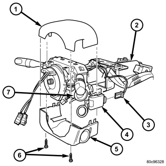
3. From below the steering column (2), remove the two screws (6) that secure the lower shroud (5) to the upper shroud (1).
4. Using hand pressure, push gently inward on both sides of the upper shroud near the parting line of the lower shroud to release the snap features that secure the two shroud halves to each other.
5. Remove both the upper and lower shrouds from the steering column.
6. Disconnect the wire harness connector (3) from the Sentry Key REmote Entry Module (SKREEM) (4).
7. The SKREEM mounting bracket features a clip that secures the module to the right lower flange of the steering column jacket. Pull downward on the connector end of the SKREEM mounting bracket to release this clip from the steering column.
8. Rotate the SKREEM and its mounting bracket downwards and then to the side away from the steering column to disengage the antenna ring from around the ignition lock cylinder housing (7).
9. Lift the multi-function switch upward off of the upper steering column housing far enough to remove the SKREEM antenna ring formation from between the ignition key release button and the multi-function switch housing.
10. Remove the SKREEM from the steering column.
INSTALLATION
WARNING: To avoid personal injury or death, on vehicles equipped with airbags, disable the supplemental restraint system before attempting any steering wheel, steering column, airbag, occupant classification system, seat belt tensioner, impact sensor, or instrument panel component diagnosis or service. Disconnect and isolate the battery negative (ground) cable, then wait two minutes for the system capacitor to discharge before performing further diagnosis or service. This is the only sure way to disable the supplemental restraint system. Failure to take the proper precautions could result in accidental airbag deployment.
1. Position the SKREEM (4) to the right side of the steering column (2).
2. Lift the multi-function switch upward off of the upper steering column housing far enough to insert the SKREEM antenna ring formation between the ignition key release button and the multi-function switch housing.
3. Slide the SKREEM antenna ring around the ignition switch lock cylinder housing (7), then rotate the SKREEM and its mounting bracket upwards and toward the steering column.
4. Align the SKREEM mounting bracket clip with the right lower flange of the steering column jacket and, push upward firmly and evenly on the connector end of the module mounting bracket to engage this clip with the steering column.
5. Reconnect the wire harness connector (3) to the SKREEM.
6. Position both the upper (1) and lower shrouds (5) onto the steering column.
7. Align the snap features on the lower shroud with the receptacles in the upper shroud and apply hand pressure to snap them together.
8. From below the steering column, install and tighten the two screws (6) that secure the lower shroud to the upper shroud. Tighten the screws to 2 N·m (18 in. lbs.).
9. If the vehicle is equipped with a tilt steering column, move the column to the fully raised position and secure it in place by moving the tilt release lever back to the locked (up) position.
10. Reconnect the negative battery cable.
NOTE: If the Sentry Key REmote Entry Module (SKREEM) (also known as the Wireless Control Module/WCM) is replaced with a new unit, a diagnostic scan tool MUST be used to initialize the new SKREEM and to program at least two Sentry Key transponders before the vehicle can be operated. (Refer to 8 - ELECTRICAL/VEHICLE THEFT SECURITY - STANDARD PROCEDURE - SKIS INITIALIZATION).