SIREN
DESCRIPTION
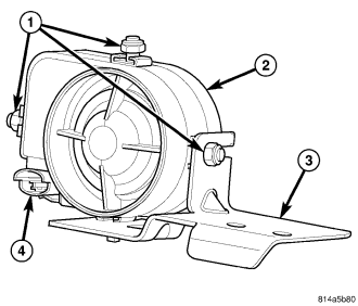
An alarm siren module (2) is part of the premium version of the Vehicle Theft Alarm (VTA) in the Vehicle Theft Security System (VTSS). The premium version of the VTA is only available in vehicles built for certain markets, where the additional features offered by this system are required. This unit is designed to provide the audible alert requirements for the premium VTA.
The alarm siren module consists of microprocessor-based electronic control circuitry, the siren, and a nickel metal hydride backup battery. All of the alarm module components are protected and sealed within a molded plastic housing. A stamped steel mounting bracket (3) is secured to the module with three stud plates and nuts (1) that fit into slotted holes at the top and each side of the bracket. Two mounting holes in the horizontal surface of the bracket are secured with screws to the right front wheel house panel front extension below and behind the right headlamp. A connector receptacle (4) extends forward from the alarm siren housing, and connects the module to the vehicle electrical system through a dedicated take out of the headlamp and dash wire harness.
The alarm siren module cannot be repaired or adjusted and, if ineffective or damaged, it must be replaced.
OPERATION
The microprocessor within the alarm siren module provides the siren unit features and functions based upon internal programming and electronic arm and disarm messages received from the Intrusion Transceiver Module (ITM) over a dedicated serial bus communication circuit. The alarm siren module receives battery voltage through a fuse in the Power Distribution Center (PDC), and receives ground through a ground location on the left inner fender shield in the engine compartment. These connections allow the alarm siren module to remain operational, regardless of the ignition switch position.
When the premium version of the Vehicle Theft Alarm (VTA) is armed, the siren module continuously monitors electronic message inputs from the ITM to sound its internal siren. While armed, the siren also enters its auto-detect mode. While in the auto-detect mode, if the siren module detects that its power supply or communication circuits are being tampered with or have been sabotaged, it will sound an audible alarm and continue to operate through its on-board backup battery. If the siren module is in its disarmed mode when its power supply or communication circuits are interrupted, the siren will not sound.
The siren module will also notify the ITM when the backup battery requires charging, and the ITM will send electronic messages that will allow the backup battery to be recharged through the battery voltage and ground circuits to the siren module only when the ignition switch is in the ON position and the engine is running. This prevents the potential discharge of the main battery while the vehicle is not being operated.
The siren will self-detect problems with its internal and external power supply and communication circuits, then send electronic messages indicating the problem to the ITM upon receiving an arm or disarm request message. The ITM will store a Diagnostic Trouble Code (DTC) for a detected siren module fault. The DTC can then be retrieved with a diagnostic scan tool through the 16-way Data Link Connector (DLC) located under the driver side lower edge of the instrument panel over the Programmable Communications Interface (PCI) data bus.
The hard wired inputs and outputs for the alarm siren module may be diagnosed using conventional diagnostic tools and procedures. Refer to the appropriate wiring information. However, conventional diagnostic methods will not prove conclusive in the diagnosis of the alarm siren module or the electronic controls or communication between other modules and devices that provide some features of the VTA system. The most reliable, efficient, and accurate means to diagnose the alarm siren module or the electronic controls and communication related to alarm siren module operation requires the use of a diagnostic scan tool. Refer to the appropriate diagnostic information.
REMOVAL
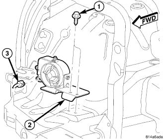
1. Disconnect and isolate the battery negative cable.
2. Disconnect the wire harness connector (3) from the connector receptacle of the alarm siren module (2).
3. Remove the two screws (1) that secure the alarm siren module to the front extension of the right front wheel house panel.
4. Remove the alarm siren module from the front extension of the right front wheel house panel.
INSTALLATION
1. Position the alarm siren module (2) onto the front extension of the right front wheel house panel.
2. Install and tighten the two screws (1) that secure the alarm siren module to the front extension of the right front wheel house panel. Tighten the screws to 6 N·m (50 in. lbs.).
3. Reconnect the wire harness connector (3) for the alarm siren module.
4. Reconnect the battery negative cable.
NOTE: If the alarm siren module has been replaced with a new unit, the new unit MUST be configured in the Intrusion Transceiver Module (ITM) before the Vehicle Theft Security System can operate as designed. The use of a diagnostic scan tool is required to configure the alarm siren module settings in the ITM. Refer to the appropriate diagnostic information.