STANDARD PROCEDURE
- STANDARD PROCEDURE - HEIGHT MEASUREMENT
- STANDARD PROCEDURE - CAMBER AND CASTER ADJUSTMENT
- STANDARD PROCEDURE - TOE ADJUSTMENT
- STANDARD PROCEDURE - CAMBER, CASTER AND TOE ADJUSTMENT
STANDARD PROCEDURE - HEIGHT MEASUREMENT
RIDE HEIGHT
NOTE: The suspension is non-adjustable.
The vehicle suspension height should be measured before performing wheel alignment procedure. Also when front suspension components have been replaced. This measure must be performed with the vehicle supporting it's own weight and taken on both sides of the vehicle.
Front and rear ride heights are not adjustable. The spring selections at assembly determine ride height for acceptable appearance of the vehicle. Ride height dimensions assume full fluids (including fuel) and zero passengers. Refer to the table below for front ride height dimensions.
Vehicle ride height audits should be performed utilizing the following procedure:
1. Drive the vehicle straight and forward on a non-tacky surface for a minimum of 20 feet to neutralize track width.
2. Bounce the front of the vehicle five times.
3. Measure and record the dimensions
FRONT RIDE HEIGHT
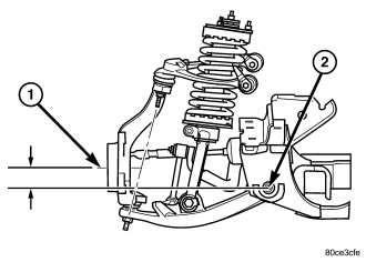
Front ride height is defined by the relative vertical distance between the spindle center line and the rear pivot point of the front lower control arm to cradle attachment. The spindle center line is to be measured at the outer wheel face (point A) (1). The rear pivot point is to be measured at the center of the cam/pivot bolt (point B) (2) at its rearward most end (nut end).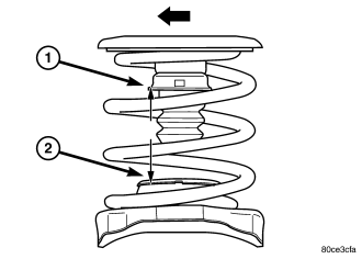
REAR RIDE HEIGHT
Rear ride height is defined by the relative vertical distance between the top of the lower spring seat strike surface and the bottom of the jounce cup (true metal to metal jounce travel). This is to be measured vertically inside the coil from the point intersecting the inboard edge and the for/aft center of the jounce cup (point C) (1) down to the strike surface (point D) (2).| Measurement | Target | Minimum | Maximum |
| Front Ride Height Distance AB | 66.5 mm Z=996.8 - 930.3 mm | 56.5 mm | 76.5 mm |
| Front Cross Ride Height Left - Right | 0.0 mm | -10.0 mm | 10.0 mm |
| Rear Ride Height Distance CD | 92.1 mm | 82.1 mm | 102.1 mm |
| Rear Cross Ride Height Left - Right | 0.0 mm | -10.0 mm | 10.0 mm |
STANDARD PROCEDURE - CAMBER AND CASTER ADJUSTMENT
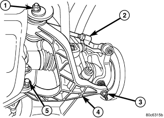
Camber and caster angle adjustments involve changing the position of the lower control arm cam bolts (1&5).
STANDARD PROCEDURE - TOE ADJUSTMENT
4X4 SUSPENSION HEIGHT MESUREMENT MUST BE PERFORMED BEFORE AN ALIGNMENT.The wheel toe position adjustment is the final adjustment.
1. Start the engine and turn wheels both ways before straightening the wheels. Secure the steering wheel with the front wheels in the straight-ahead position.
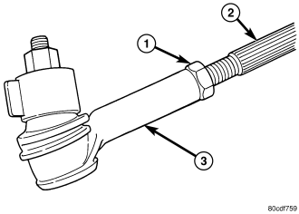
2. Loosen the tie rod jam nuts (1).
NOTE: Each front wheel should be adjusted for one-half of the total toe position specification. This will ensure the steering wheel will be centered when the wheels are positioned straight-ahead.
3. Adjust the wheel toe position by turning the tie rod as necessary .
4. Tighten the tie rod jam nut (1) to 75 N·m (55 ft. lbs.).
5. Verify the specifications
6. Turn off engine.
STANDARD PROCEDURE - CAMBER, CASTER AND TOE ADJUSTMENT
Camber and caster angle adjustments involve changing the position of the lower suspension arm cam bolts.
CASTER
Moving the rear position of the cam bolt in or out, will change the caster angle significantly and camber angle only slightly. To maintain the camber angle while adjusting caster, move the rear of the cam bolt in or out. Then move the front of the cam bolt slightly in the opposite direction.
To increase positive caster angle, move the rear position of the cam bolt outward (from the engine). Move the front of cam bolt inward (toward the engine) slightly until the original camber angle is obtained.
CAMBER
Move both of the cam bolts together in or out. This will change the camber angle significantly and caster angle slightly.
After adjustment is made tighten the cam bolt nuts to proper torque specification.
TOE ADJUSTMENT
The wheel toe position adjustment is the final adjustment.
1. Start the engine and turn wheels both ways before straightening the wheels. Secure the steering wheel with the front wheels in the straight-ahead position.
2. Loosen the tie rod jam nuts.
NOTE: Each front wheel should be adjusted for one-half of the total toe position specification. This will ensure the steering wheel will be centered when the wheels are positioned straight-ahead.
3. Adjust the wheel toe position by turning the tie rod as necessary .
4. Tighten the tie rod jam nut to 75 N·m (55 ft. lbs.).
5. Verify the specifications
6. Turn off engine.