COMPASS/MINI-TRIP COMPUTER
DESCRIPTION
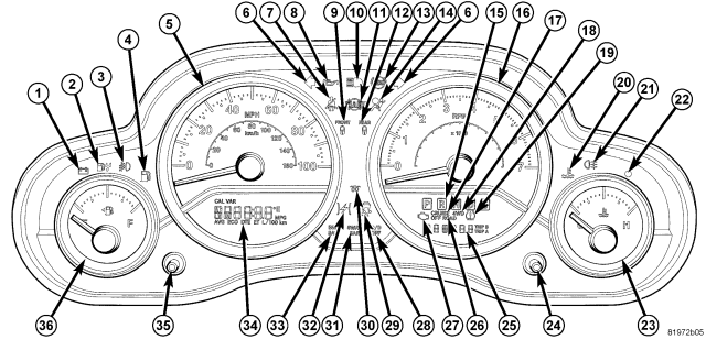
The Compass Mini Trip Computer (CMTC) features two driver-interactive displays. The display located in the lower left part of the instrument cluster (34) at the bottom of the speedometer (5) displays the compass/temperature and trip computer functions. The display located in the lower right part of the instrument cluster (25) at the bottom of the tachometer (16) displays the odometer related functions. This system conveniently allows the driver to select a variety of useful information by pressing the left instrument cluster button (35) and right instrument cluster button (24). Once a particular system is displayed, pressing and holding one of the instrument cluster buttons once will clear the resettable function currently being displayed. Reset will only occur if a resettable function is currently being displayed. The CMTC displays information related to the following:
- System Status
- Vehicle information warning message displays
- Compass display
- Outside temperature display
- Trip computer functions
The CMTC system is comprised of several different components. Those components are:
- Instrument Cluster (sometimes referred to as Cab Compartment Node)
- Left instrument cluster button
- Right instrument cluster button
- Ambient Temperature Sensor
- Remote Compass Module (RCM)
- Controller Area Network (CAN) Data Bus
- Local Interface Network (LIN) Data Bus
The CMTC display and the instrument cluster buttons are part of the Instrument Cluster assembly and cannot be serviced as separate components. If the display or button are inoperative the complete Instrument Cluster assembly must be replaced, (Refer to 8 - ELECTRICAL/INSTRUMENT CLUSTER - REMOVAL).
OPERATION
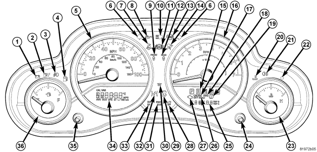
The Compass Mini Trip Computer (CMTC) uses both non-switched and ignition switched sources of battery current so that some of its features remain operational at any time, while others may only operate with the ignition switch in the ON position. When the ignition switch is turned to the ON position, the CMTC display (34) will return to the last function being displayed before the ignition was turned to the OFF position.
The CMTC system is comprised of several different components that communicate over the Controller Area Network (CAN) and Local Interface Network (LIN) Data Buses. If the system is inoperative a scan tool and the appropriate diagnostic information must be used to diagnose the system and related data buses.
The left instrument cluster button (35) is used to navigate through the different functions of the CMTC system. Pressing and releasing the button will scroll through the following displays:
- Compass/Temperature
- Average Fuel Economy (AVG ECO)
- Distance To Empty (DTE)
- Elapsed Time
Once a particular system is displayed, pressing and holding the left instrument cluster button (35) once will clear the resettable function currently being displayed. Reset will only occur if a resettable function is currently being displayed.
The right instrument cluster button (24) is used to navigate through the different functions of the odometer system. Pressing and releasing the button will scroll through the following displays:
- Trip Odometer (ODO)
- Trip A
- Trip B
Once a particular system is displayed, pressing and holding the right instrument cluster button (24) once will clear the resettable function currently being displayed. Reset will only occur if a resettable function is currently being displayed.
CMTC DISPLAY MODES
SYSTEM STATUS MODE
System display mode displays warnings and user interaction messages on the CMTC display. The driver can scroll to view multiple messages by using the left instrument cluster button.
When the appropriate conditions exist, the CMTC displays the following messages:
- Door(s) Ajar
- Swing Gate Ajar
- Loose Fuel Cap
- No Ignition Off Draw (IOD) Fuse
- Electronic Stability Program (ESP) Off
These messages can be manually turned off by pressing the left instrument cluster button.
COMPASS/TEMPERATURE
Compass heading and outside temperature are displayed on the CMTC display screen. One of eight compass headings to indicate the direction the vehicle is facing (N, S, E, W, NE, NW, SE, SW) and one of 15 compass variance settings can be displayed. Outside temperature is displayed in °C (degrees Celsius) or °F (degrees Fahrenheit).
AVERAGE FUEL ECONOMY (AVG ECO)
Shows the average fuel economy since the last reset. When the fuel economy is reset, the display will read “RESET” or show dashes for two seconds. Then, the history information will be erased, and the averaging will continue from where it was before the reset.
DISTANCE TO EMPTY (DTE)
NOTE: Significant changes in driving style or vehicle loading will greatly affect the actual drivable distance of the vehicle, regardless of the DTE displayed value.
Shows the estimated distance that can be travelled with the fuel remaining in the tank. This estimated distance is determined by a weighted average of the instantaneous and average fuel economy, according to the current fuel tank level. This is not resettable.
ELAPSED TIME
Shows the total elapsed time of travel since the last reset when the ignition switch is in the ON position.
TRIP ODOMETER (ODO)
Shows the distance traveled since the last reset. Press and release the right instrument cluster button to switch from the trip odometer to trip A or trip B function. Press and hold the right instrument cluster button while trip odometer is displayed will reset the trip odometer to 0 miles.
TRIP A
Shows the distance traveled for trip A since the last trip A reset. Press and hold the right instrument cluster button while trip A is displayed will reset the trip A to 0 miles.
TRIP B
Shows the distance traveled for trip B since the last trip B reset. Press and hold the right instrument cluster button while trip B is displayed will reset the trip B to 0 miles.
REMOVAL - REMOTE COMPASS MODULE
WARNING: On vehicles equipped with airbags, disable the airbag system before attempting any steering wheel, steering column, or instrument panel component diagnosis or service. Disconnect and isolate the negative battery (ground) cable, then wait two minutes for the airbag system capacitor to discharge before performing further diagnosis or service. This is the only sure way to disable the airbag system. Failure to take the proper precautions could result in accidental airbag deployment and possible personal injury or death.
1. Disconnect and isolate the battery negative cable.
2. Using a trim stick C-4755 or equivalent, remove the upper instrument panel cover located over the center bezel and radio.
3. Remove the screws securing the Remote Compass Module (RCM) to the upper instrument panel cover.
4. Disconnect the RCM electrical connector and remove the RCM from the vehicle.
INSTALLATION - REMOTE COMPASS MODULE
NOTE: The Remote Compass Module (RCM) must be calibrated after installation. (Refer to 8 - ELECTRICAL/MESSAGE CENTER/COMPASS/MINI-TRIP COMPUTER - STANDARD PROCEDURE - MANUAL COMPASS CALIBRATION) for the appropriate procedure.
1. Position the Remote Compass Module (RCM) onto the upper instrument panel cover.
2. Install the screws that secure the RCM to the upper instrument panel cover.
3. Connect the RCM electrical connector.
4. Install the upper instrument panel cover located over the center bezel and seat fully.
5. Connect the battery negative cable.
6. Calibrate the RCM, (Refer to 8 - ELECTRICAL/MESSAGE CENTER/COMPASS/MINI-TRIP COMPUTER - STANDARD PROCEDURE - MANUAL COMPASS CALIBRATION).