BATTERY CABLES
DESCRIPTION
The battery cables are large gauge, stranded copper wires sheathed within a heavy plastic or synthetic rubber insulating jacket. The wire used in the battery cables combines excellent flexibility and reliability with high electrical current carrying capacity. The battery cables feature a clamping type female battery terminal made of stamped sheet metal that is die cast onto one end of the battery cable wire. A pinch-bolt and nut are installed at the open end of the female battery terminal clamp. Large eyelet type terminals are crimped onto the opposite end of the battery cable wire and then soldered. The battery positive cable wires feature a larger female battery terminal clamp to allow connection to the larger battery positive terminal post. The battery negative cable wires have a smaller female battery terminal clamp.
Both the battery positive and negative cables are available for service replacement only as a unit with the battery wire harness, which may include portions of the wiring circuits for the generator and other components on some vehicles.
OPERATION
The battery cables connect the battery terminal posts to the vehicle electrical system. These cables also provide a path back to the battery for electrical current generated by the charging system for restoring the voltage potential of the battery. The female battery terminal clamps on the ends of the battery cable wires provide a strong and reliable connection of the battery cable to the battery terminal posts. The terminal pinch bolts allow the female terminal clamps to be tightened around the male terminal posts on the top of the battery. The eyelet terminals secured to the opposite ends of the battery cable wires from the female battery terminal clamps provide secure and reliable connection of the battery cables to the vehicle electrical system.
One wire has an eyelet terminal that connects the battery positive cable to the B(+) terminal stud of the Totally Integrated Power Module (TIPM), and the other wire has an eyelet terminal that connects the battery positive cable to the B(+) terminal stud of the engine starter motor solenoid. The battery negative cable terminal clamp has one wire as an eyelet terminal that connects the battery negative cable to the vehicle powertrain through a ground connection, typically on the engine cylinder block.
REMOVAL
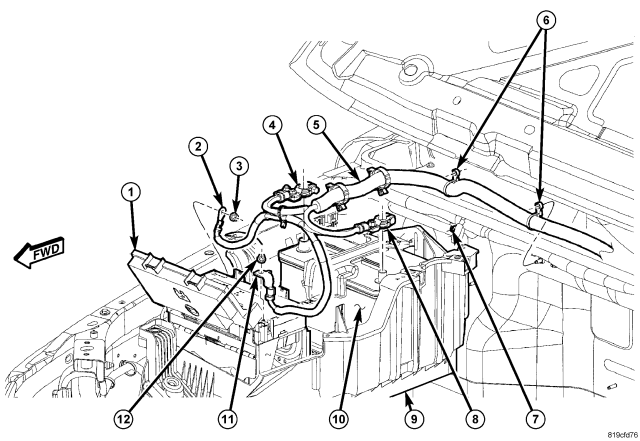
WARNING: Remove metallic jewelry to avoid injury by accidental arcing of battery current.
WARNING: The battery negative and positive cable polarity are different from the gasoline engine equipped vehicles to the diesel engine equipped vehicles. Please note the location of the positive and negative cables prior to service of the battery or related components.
NOTE: Left hand drive gasoline engine shown, left hand drive diesel similar. Right hand drive gasoline and diesel similar with the battery and related components packaged on the left side of the engine compartment.
1. Loosen the pinch clamp bolt and disconnect and isolate the battery negative cable (8).
2. Loosen the pinch clamp bolt and disconnect the battery positive cable (4).
3. Remove the positive cable retaining nut (12) from the mounting stud on the Totally Integrated Power Module (1). Remove the cable (11) from the stud.
4. Remove the negative cable retaining nut (3) from the mounting stud on the inner fender. Remove the cable (2) from the stud.
5. Disconnect the cable assembly (5) routing clips (6) from the mounting studs (7).
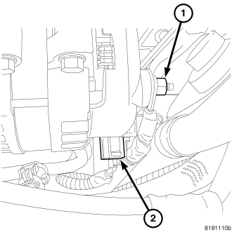
6. Remove the battery cable nut (1) from the B+ terminal of the generator. Remove the cable from the generator.
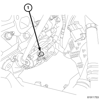
7. Remove the battery cable from the B+ terminal of the starter motor (1).
8. Remove the negative battery cable from the engine block ground.
9. One at a time, trace any remaining battery cable retaining pushpins, fasteners and routing clips until the cables are free from the vehicle.
10. Remove the battery cables from the engine compartment.
INSTALLATION
WARNING: Remove metallic jewelry to avoid injury by accidental arcing of battery current.
1. Position the battery cables in the engine compartment.
2. One at a time, install the battery cable retaining pushpins, fasteners and routing clips until the cables are installed exactly where they were in the vehicle.
3. Install the negative battery cable to the engine block ground.
4. Connect the battery cable to the B+ terminal of the starter motor (1). Tighten the cable nut to 13 N·m (115 in. lbs.).
5. Connect the battery cable to the B+ terminal of the generator (1). Tighten the cable nut to 14 N·m (125 in. lbs.).
WARNING: The battery negative and positive cable polarity are different from the gasoline engine equipped vehicles to the diesel engine equipped vehicles. Please note the location of the positive and negative cables prior to service of the battery or related components.
NOTE: Left hand drive gasoline engine shown, left hand drive diesel similar. Right hand drive gasoline and diesel similar with the battery and related components packaged on the left side of the engine compartment.
6. Connect the cable assembly (5) routing clips (6) to the mounting studs (7).
7. Install the nut (3) securing the negative cable (2) to the body ground stud. Tighten the cable nut to 12 N·m (9 ft. lbs.)
8. Install the nut (12) securing the Totally Integrated Power Module (TIPM) cable (11) to the battery cable stud (5).
9. Connect the battery positive cable (4). Tighten the cable clamp nut to 5 N·m (45 in. lbs.)
10. Connect the battery negative cable (8). Tighten the cable clamp nut to 5 N·m (45 in. lbs.)