CONTROL-A/C HEATER
DESCRIPTION
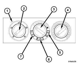
The A/C-heater control (1) for the manual temperature control (MTC) single zone system allows one temperature setting for the entire vehicle. All controls are identified by ISO graphic symbols.
The heating-A/C system uses a combination of electrical and cable operated controls. These controls provide the vehicle operator with a number of setting options to help control the climate and comfort within the vehicle.
The A/C-heater control is located in the instrument panel and contains:
- a rotary control for mode control of the discharged air (2).
- a rotary control for blower motor speed selection and to turn the blower motor off (3).
- a rotary control for temperature control of the discharged air (4).
- a push-button control with indicator light for to turn the rear window defogger system on and off (5), when equipped.
- a push-button control with indicator light for recirculation control of the discharged air (6).
- a push-button control with indicator light to turn the A/C system on and off (7).
The A/C-heater control cannot be adjusted or repaired and it must be replaced if found inoperative or damaged. The control knobs for the A/C-heater control are available for service replacement.
REMOVAL
WARNING: Disable the airbag system before attempting any steering wheel, steering column, or instrument panel component diagnosis or service. Disconnect and isolate the negative battery (ground) cable, then wait two minutes for the airbag system capacitor to discharge before performing further diagnosis or service. This is the only sure way to disable the airbag system. Failure to take the proper precautions could result in accidental airbag deployment and possible personal injury or death.
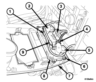
NOTE: Typical A/C-heater control and center bezel shown.
1. Disconnect and isolate the negative battery cable.
2. Disengage the center bezel (7) from the instrument panel and disconnect the wiring harness connectors from the power outlets and any switches, as equipped (refer to 23 - BODY/INSTRUMENT PANEL/BEZEL-CENTER - REMOVAL).
NOTE: To aid in reinstallation, note the installed positions of the control cables prior to removal.
3. Using a small screwdriver or similar tool, disengage the retaining clips that secure the control cables (1 and 9) to the back of the A/C-heater control (8).
4. Using a small screwdriver or similar tool, disengage the retaining clips that secure the control cables to the mode control sector gear (2) and the temperature control sector gear (5).
5. Disconnect the wire harness connectors (3 and 4) from the rear of the A/C-heater control and place the center bezel on a work bench.
6. Remove the four screws (6) that secure the A/C-heater control to the back of the center bezel and remove the control.
INSTALLATION
NOTE: Typical A/C-heater control and center bezel shown.
1. Install the A/C-heater control (8) into the instrument panel center bezel (7).
2. Install the four screws (6) that secure the A/C-heater control to the center bezel. Tighten the screws to 2 N·m (17 in. lbs.).
3. Position the center bezel to the instrument panel and connect the wire harness connectors (3 and 4) to the back of the A/C-heater control.
NOTE: Install the mode control cable onto the A/C heater control first. Then install the temperature control cable.
4. Connect the control cables (1 and 9) to the mode door control sector gear (2) and the temperature control sector gear (5) and fully engaged the retaining clips. Make sure the retaining clips are fully engage to the sector gears.
5. Connect the control cables to the back of the A/C-heater control and fully engage the retaining clips. Make sure the retaining clips are fully engaged to the back of the A/C-heater control.
6. Connect the wire harness connectors to the switches and power outlets, as equipped and install the center bezel to the instrument panel (refer to 23 - BODY/INSTRUMENT PANEL/BEZEL-CENTER - INSTALLATION).
7. Reconnect the negative battery cable.