OUTLETS-AIR
DESCRIPTION
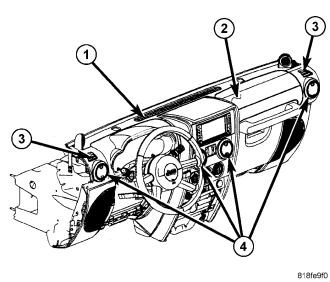
NOTE: LHD model shown. RHD model similar.
There is one defroster air outlet (1) located on the top of the instrument panel (2). The airflow from the defroster outlet is directed by fixed vanes in the outlet and cannot be adjusted. The defroster air outlet is not serviceable from the instrument panel cover (refer to 23 - BODY/INSTRUMENT PANEL/INSTRUMENT PANEL COVER - REMOVAL).
There are two side window demister air outlets (3). One located on each end of the instrument panel top cover. The airflow from the side window demister air outlets is directed by fixed vanes in the outlets and cannot be adjusted. The side window demister air outlets are not serviceable from the instrument panel cover (refer to 23 - BODY/INSTRUMENT PANEL/INSTRUMENT PANEL COVER - REMOVAL).
There are four round instrument panel air outlets (4). One air outlet is located near each outboard end of the instrument panel facing the rear of the vehicle and two air outlets are located at the top of the instrument panel center bezel. Each of the instrument panel air outlets contain movable vanes that can direct or shut off the flow of the conditioned air leaving each of the instrument panel outlets. Each instrument panel air outlet can be serviced separately.
REMOVAL
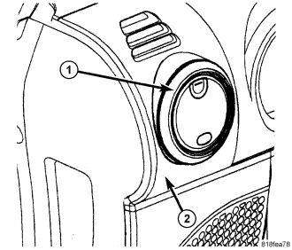
1. Rotate each air outlet (1) counter-clockwise to disengage its retaining tabs.
NOTE: If the foam seal on the air outlet is deformed or damaged, it must be replaced.
2. Carefully pull each air outlet straight out of the instrument panel (2).
INSTALLATION
NOTE: If the foam seal on the air outlet is deformed or damaged, it must be replaced.
1. Position each air outlet (1) straight into the instrument panel (2).
2. Rotate each air outlet clockwise to engage its retaining tabs. Make sure the retaining tabs are fully engaged.