HEAD-CYLINDER
DESCRIPTION
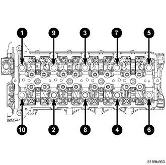
The 2.8L aluminum, overhead valve cylinder head is torqued in a cross pattern. The cylinder head itself is not resurfacable.
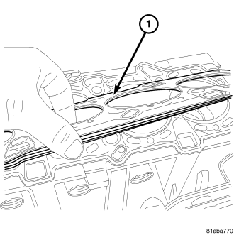
1. The cylinder head uses a selectable Multi-layered Steel gasket that is available in three sizes.
REMOVAL
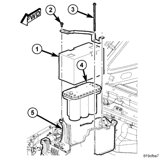
1. Connect the battery.
2. Remove the battery.
3. Remove the accessory drive belt.
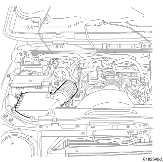
4. Remove the intake air housing.
5. Fill the cooling system.
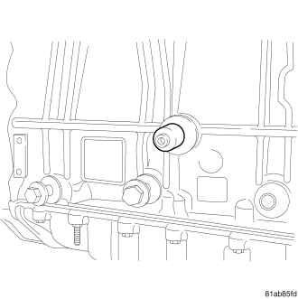
6. Remove the crankshaft locking tool.
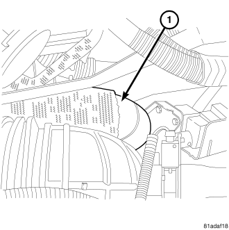
7. Remove the charge air cooler outlet hose.
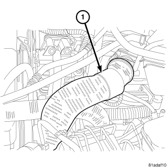
8. Remove the charge air cooler inlet hose.
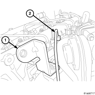
9. Remove the high pressure fuel feed line (2).
10. Remove the generator brace bolt (1).
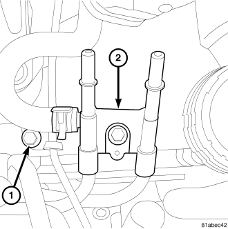
11. Disconnect the fuel return lines.
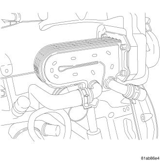
12. Remove the EGR cooler.
13. Remove the EGR cooler coolant lines.
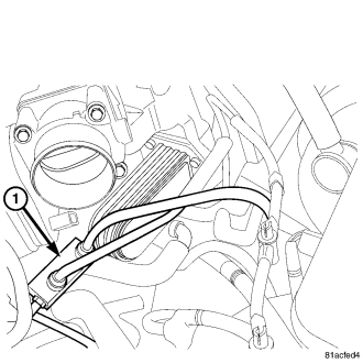
14. Remove the fuel block (1).
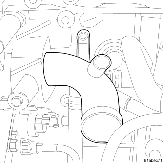
15. Disconnect the coolant lines from the thermostat housing.
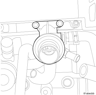
16. Remove the thermostat housing.
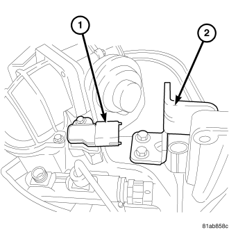
17. Disconnect the Baro sensor (1).
18. Remove the Baro sensor.
19. Remove the generator brace bolt (2).
20. Remove the throttle plate assembly.
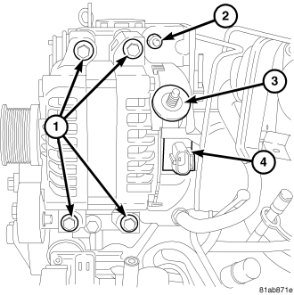
21. Remove the generator bracket.
22. Remove the generator.
23. Connect the generator connectors (4).
24. Connect the generator feed wire (3).
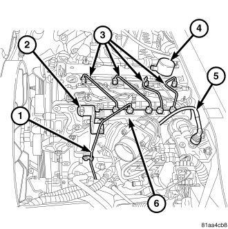
25. Remove the fuel lines (3).
26. Disconnect the fuel rail solenoid (2).
27. Disconnect the fuel rail pressure sensor.
28. Remove the fuel rail.
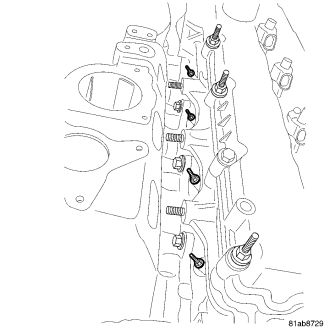
29. Disconnect and position aside the glow plug harness.
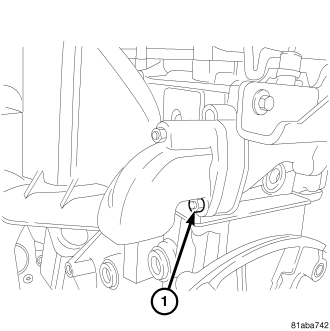
30. Remove the intake manifold.
31. Remove the intake manifold bolts.
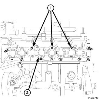
32. Remove the intake manifold gasket.
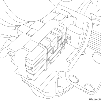
33. Disconnect the turbocharger module.
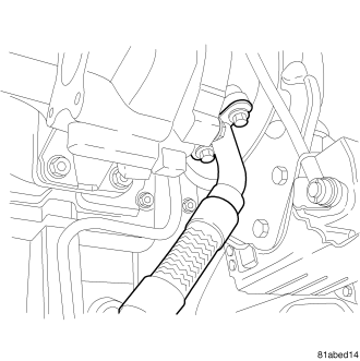
34. Remove the turbocharger oil return line.
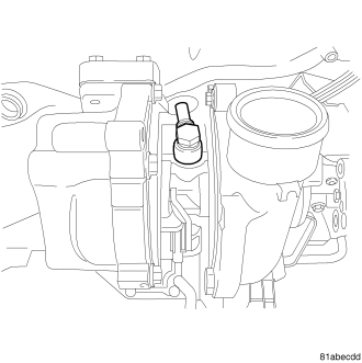
35. Remove the turbocharger nuts.
36. Remove the turbocharger oil feed line.
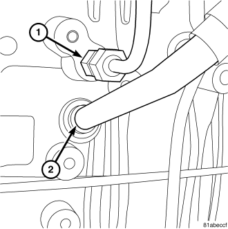
37. Remove the turbocharge oil lines from the engine block.
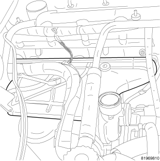
38. Remove the exhaust manifold.
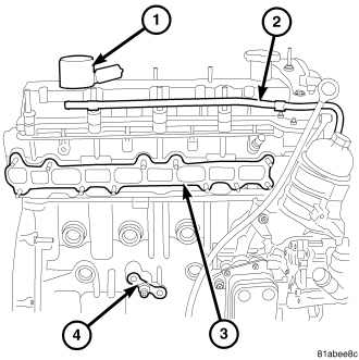
39. Remove the vacuum line from the vacuum pump.
40. Remove the vacuum line (2) from the camshaft cover.
41. Remove the exhaust manifold gasket (3).
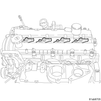
42. Disconnect the fuel injectors.
43. Remove the fuel injectors.
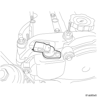
44. Disconnect the CMP.
45. Remove the CMP.
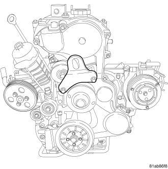
46. Remove the front engine lifting bracket.
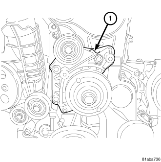
47. Remove the idler pulley bracket (1).
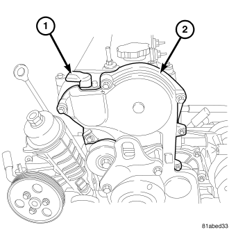
48. Remove the upper front cover.
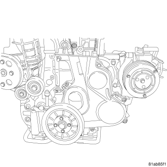
NOTE: The crankshaft sprocket bolt is a L.H. thread.
49. Remove the crankshaft damper (R.H thread).
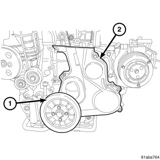
50. Remove the lower front cover.
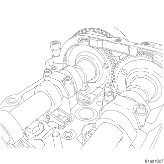
51. Make sure that the timing dimples on the back of the camshaft gears are lined up horizontally.
52. Install the camshaft locking tool.
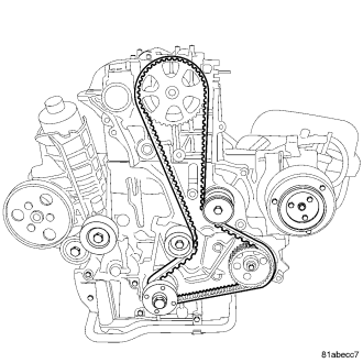
53. Remove the timing belt.
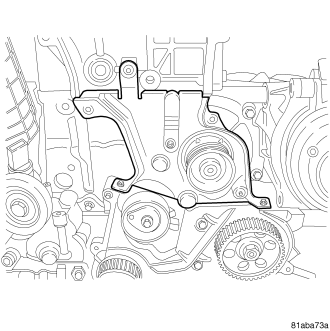
54. Remove the inner front cover.
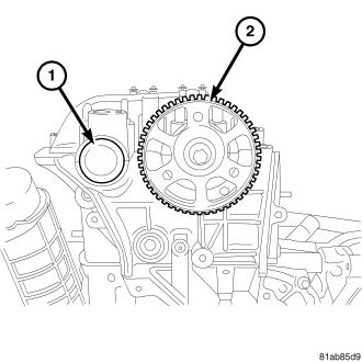
55. Remove the camshaft sprocket (2).
56. Remove the exhaust camshaft oil seal (1).
57. Remove the camshaft sprocket cover.
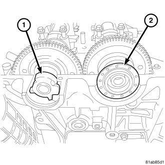
58. Remove the intake camshaft oil seal (2).
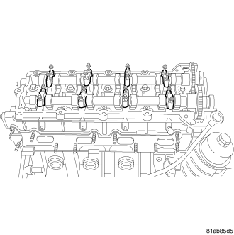
59. Using a circular pattern, loosen the camshaft cap bolts.
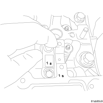
NOTE: Observe the position marks on the cylinder head and camshaft cap. Always replace the camshaft cap to its original location.
60. Remove the camshaft caps.
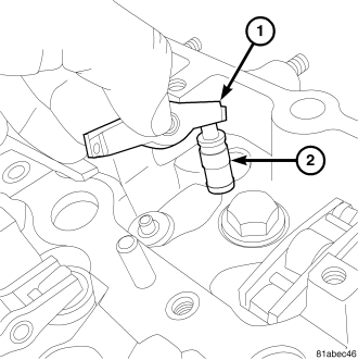
NOTE: Observe the position of the rocker arms and lifters. Always return the rocker arms and lifters to their original location.
61. Remove the rocker arms (1) and hydraulic lifters (2).
62. Remove the cylinder head.
CLEANING
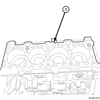
Thoroughly clean the engine cylinder head and cylinder block mating surfaces. Clean the intake and exhaust manifold and engine cylinder head mating surfaces. Remove all gasket material and carbon.
Check to ensure that no coolant or foreign material has fallen into the tappet bore area.
Remove the carbon deposits from the combustion chambers and top of the pistons.
INSPECTION
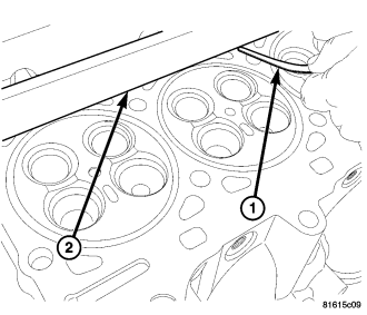
CAUTION: The cylinder head surface and straight edge must be absolutely clean before the flatness measurement is taken. DO NOT check flatness across the combustion chamber area or on the marks left by the gasket stopper.
Use a cleaned straight edge (2) and feeler (1) gauge to check the flatness. Lie the straight edge (2) parallel across the cooling ports. Measure before each combustion chamber toward the outer edge of the cylinder head, above and below each combustion chamber, between each combustion chamber, top and bottom, on the cylinder head and block mating surfaces. The maximum allowed warpage is 0.075mm (0.003 in.).
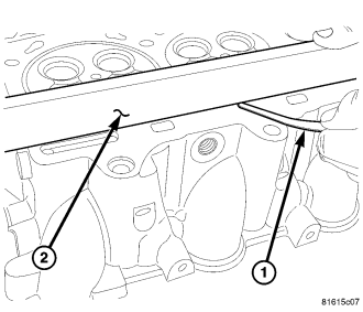
The minimum cylinder head thickness is 89.95mm (3.541 in.).
INSTALLATION
1. Make sure the crankshaft locking tool is in place.
2. Install the head gasket (1).
3. Install the cylinder head.
4. Install the cylinder head bolts in the illustrated pattern. Torque the bolts to 30 nm (22 lbs. ft.).
5. Repeat the pattern, turning the bolts an additional 85°. Repeat the pattern twice more, turning 85° each time for a total of 255°.
6. Install the rocker arms (1) and hydraulic lifters (2). Make sure to return the lifters and arms to their original position.
NOTE: Observe the position marks on the cylinder head and camshaft cap. Always replace the camshaft cap to its original location.
7. Install the camshaft caps.
8. Loosely install the camshaft bolts finger tight.
9. Make sure that the timing dimples on the back of the camshaft gears are lined up horizontally.
NOTE: The engine is not in time with the camshaft dots facing each other. The camshafts are in time with each other. The camshafts are set so that the dots face each other, and then the camshaft locking tool ensures that the camshafts are properly positioned at 90° ATDC.
10. Install the camshaft locking tool.
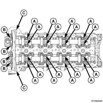
11. The camshaft bolts have 3 different bolt sizes.
- Bolts A are M6 35
- Bolts B are M6 45
- Bolts C are M6 stud bolts.
12. Put a thin bead of Loctite 510 (or equivalent) on the front camshaft cap (the cap that are secured by bolts “b”).
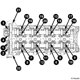
13. Following the illustrated pattern, torque the camshaft cap bolts to 11 Nm (98 lbs. in.).
14. Install the intake camshaft oil seal.
15. Install the camshaft sprocket cover.
16. Install the camshaft sprocket (2). Torque the bolt to 64 Nm (47 lbs. ft.)
17. Install the exhaust camshaft oil seal (1).
18. Install the inner front cover. Torque the bolts to 11 Nm (97 lbs. in.).
NOTE: The crankshaft sprocket bolt is a L.H. thread.
19. Install the crankshaft sprocket. Torque the bolt to 64 Nm (45 Lbs. ft.).
20. Install the timing belt. (Refer to 9 - ENGINE/VALVE TIMING/TMNG BELT/CHAIN TENSIONER&PULLEY - ADJUSTMENTS)
21. Install the lower front cover. Torque the bolts to 11 Nm (97 lbs. in.).
22. Install the crankshaft damper. Torque the bolt to 32 Nm (23 lbs. ft.).
23. Install the upper front cover. torque the bolts to 11 nm (97 lbs. in.).
24. Install the idler pulley bracket (1) and torque the bolts to 45 nm (33 lbs. ft.).
25. Install the front engine lifting bracket and toque the bolts to 45 nm (33 lbs. ft.).
26. Install the CMP. Torque the SMP sensor bolt to 11 Nm (97 lbs. in.).
27. Connect the CMP.
28. Install the fuel injectors. Torque the fuel injector bolts to 33 Nm (24 lbs. ft.).
29. Connect the fuel injectors.
30. Install the vacuum line to the vacuum pump.
31. Install the vacuum line (2) to the camshaft cover.
32. Install the exhaust manifold gasket (3).
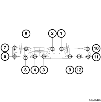
33. Install the exhaust manifold using the above sequence. Torque the bolts to 35 nm (29 lbs. ft.)
34. Install the turbocharge oil lines to the engine block. Torque the bolt to 32 Nm (23 lbs. ft.).
35. Install the turbocharger nuts and torque to 32 Nm (23 lbs. ft.).
36. Install the turbocharger oil feed line. Torque the oil feed line bolt to 24 Nm (18 lbs. ft.).
37. Install the turbocharger oil return line. Torque the oil return line bolts to 15 Nm (133 lbs. in.).
38. Connect the turbocharger module.
39. Install the intake manifold gasket.
40. Install the intake manifold.
41. Install the intake manifold bolts. Torque the intake manifold bolts to 36 Nm (26 lbs. ft.).
42. Install the glow plugs. Torque the glow plugs to 14 Nm (124 lbs. in.).
43. Position and connect the glow plug harness.
44. Install the fuel rail. Torque the fuel rail nuts to 24 Nm (18 lbs. ft.)
45. Loosely install the fuel lines (3) onto the fuel injectors and the fuel rail.
46. Torque the fuel lines at the fuel rail to 20 Nm (177 lbs. in.).
47. Torque the fuel lines at the fuel injectors to 28 Nm (20 lbs. in.).
48. Loosely install the high pressure fuel feed line to the high pressure pump and the fuel rail.
49. Torque the high pressure fuel line at the fuel rail to 20 Nm (15 lbs. ft.).
50. Torque the high pressure fuel line at the fuel pump to 28 Nm (20 lbs. ft.)
51. Install the high pressure fuel line bracket bolt and torque to 15 Nm (133 lbs. in.).
52. Connect the fuel rail solenoid (2).
53. Connect the fuel rail pressure sensor.
54. Install the generator bracket. Torque the bolts to 45 Nm (33 lbs. ft.).
55. Install the generator. Torque the bolts to 33 Nm (24 lbs. ft.)
56. Connect the generator connectors (4).
57. Connect the generator feed wire (3).
58. Connect the Baro sensor (1).
59. Install the Baro sensor.
60. Install the generator brace bolt (2).
61. Install the throttle plate assembly.
62. Install the thermostat housing.
63. Connect the coolant lines from the thermostat housing.
64. Install the EGR cooler. Torque the bolts to 11 nm (97 lbs. in.)
65. Install the EGR cooler coolant lines.
66. Install the fuel block.
67. Connect the fuel return lines.
68. Install the high pressure fuel feed line (2).
69. Install the generator brace bolt (1).
70. Install the charge air cooler inlet hose.
71. Install the charge air cooler outlet hose.
72. Install the accessory drive belt.
73. Install the intake air housing.
74. Fill the cooling system.
75. Connect the battery.