SPROCKET(S)-TIMING BELT AND CHAIN
REMOVAL
1. Disconnect negative battery cable.
2. Remove cooling fan and fan drive viscous clutch assembly (Refer to 7 - COOLING/ENGINE/FAN DRIVE VISCOUS CLUTCH - REMOVAL) .
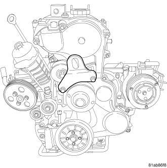
3. Remove the front engine lifting bracket.
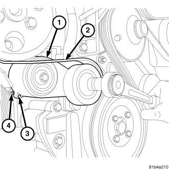
4. Loosen the timing belt tension by rotating the timing belt tensioner until holes 3 and 4 are lined up.
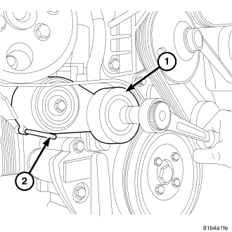
5. When the holes in the timing belt tensioner are aligned, use a drift to lock the tensioner in place.
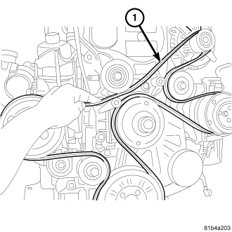
6. Remove the accessory drive belt.
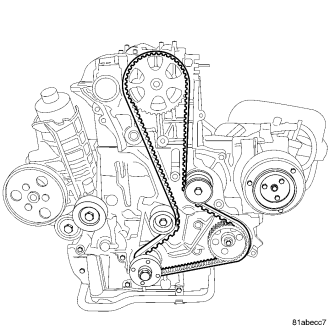
CAUTION: BEFORE REMOVING THE TIMING BELT, THE ENGINE MUST BE PLACED AT 90° AFTER TDC. FAILURE TO DO SO MAY RESULT IN VALVE AND/OR PISTON DAMAGE DURING ASSEMBLY.
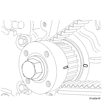
7. Bring piston #1 to 90° ATDC by turning crankshaft clockwise until the mark on the crankshaft lines up with the mark on the front cover.
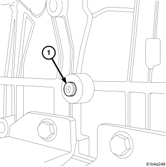
8. Remove the plug for the crankshaft locking tool. The crankshaft locking tool is installed in the left side of the engine slightly rearward of the engine mount.
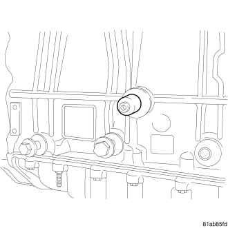
9. Install the crankshaft locking tool into the engine block. Make sure that the crankshaft locking tool body is threaded into the engine block and the bolt is threaded into the crankshaft.
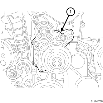
10. Remove the idler pulley bracket.
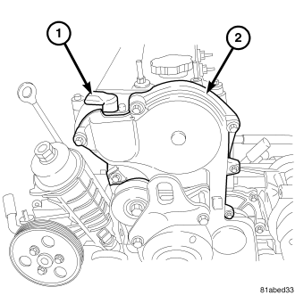
11. Disconnect the CMP sensor (1).
12. Remove the CMP sensor bolt.
13. Remove the CMP (1) sensor.
14. Remove the upper front cover (2).
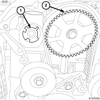
15. Remove the exhaust camshaft seal (1) from the cylinder head.
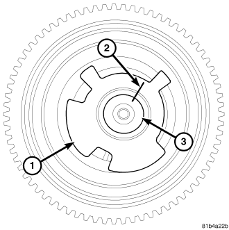
16. Use a paint pen to mark the location of the reluctor wheel (1) on the camshaft (2).
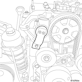
17. Install the camshaft timing tool on the exhaust camshaft.
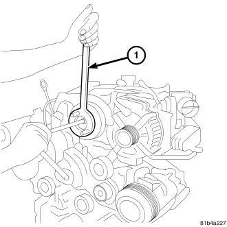
18. Use VM 1055 to hold the intake camshaft sprocket.
19. Remove the bolt from the intake camshaft sprocket.
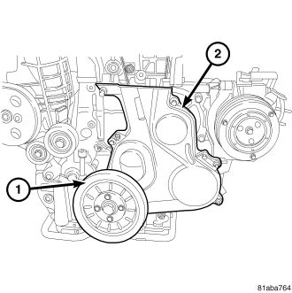
20. Remove the 4 bolts from the vibration damper (1).
21. Remove the vibration damper (1).
22. Unscrew the lower front cover bolts. The lower front cover bolts remain in the lower front cover.
23. Remove the lower front cover (2).
24. Loosen timing belt tensioner and remove timing belt.
25. Remove the camshaft sprocket bolt.
26. Remove the camshaft sprocket.
NOTE: The crankshaft sprocket is a left handed thread.
27. Remove the crankshaft sprocket bolt.
28. Remove the crankshaft sprocket.
INSTALLATION
1. Make sure that the crankshaft locking tool is in place. The crankshaft locking tool is installed in the left side of the engine block, right behind the motor mount. Make sure that the crankshaft locking tool body is threaded into the engine block and the bolt is threaded into the crankshaft.
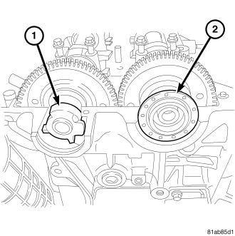
2. Install the intake camshaft oil seal (2).
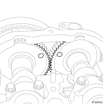
3. Make sure the camshafts are timed to each other by rotating the camshafts until the dots line up.
NOTE: The camshafts are only timed to each other when the dots line up. Use the camshaft locking tool to set the camshafts to 90° ATDC.
4. Install the cylinder head cover. (Refer to 9 - ENGINE/CYLINDER HEAD/CYLINDER HEAD COVER(S) - INSTALLATION)
5. Install the camshaft locking tool..
6. Install VM 1055 on the intake camshaft sprocket.
7. Using VM 1055 to secure the camshaft sprocket, torque the camshaft sprocket (2) bolt to 64 N·m (47 ft.lbs.).
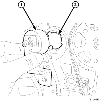
8. Remove the camshaft locking tool.
9. Verify that the reluctor wheel has not moved on the camshaft. If the reluctor wheel has spun on the camshaft during the assembly process, replace the camshaft.
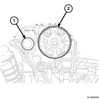
10. Install the exhaust camshaft oil seal (1).
11. Make sure that the mark on the crankshaft sprocket is pointing at the mark on the engine.
NOTE: The crankshaft sprocket bolt is a left handed thread.
12. Install the crankshaft sprocket.
13. Install the crankshaft sprocket bolt. Torque the crankshaft sprocket bolt to 64 Nm (47 lbs. ft.).
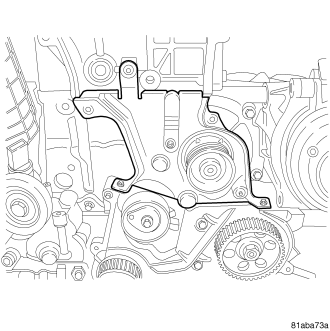
14. Install the inner front cover. Torque the bolts to 11 Nm (97 lbs. in.).
NOTE: DO NOT remove the timing belt from the package until it's ready to be installed. DO NOT expose timing belt to oil, grease or water contamination. DO NOT crimp belt at a sharp angle. DO NOT clean belt, pulleys or tensioner with solvent. Check that pulleys and bearings are not seized or damage before installing belt.
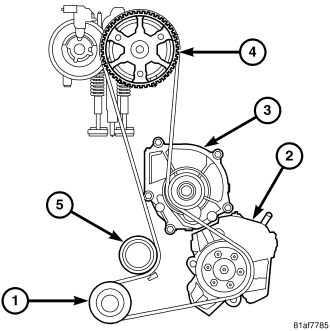
15. Install the timing belt on the components in the following order.
- Crankshaft sprocket (1).
- High pressure fuel pump (2).
- Water pump pulley (3).
- Intake camshaft pulley (4).
- Timing belt tensioner (5).
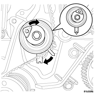
16. Adjust the timing belt tensioner (turn it clockwise) by lining up the center notch with the aluminum cover dowel pin. Tighten the retaining bolt to 45 N·m (33 lbs. ft.)..
17. Install the lower front cover. Torque the bolts to 11 N·m (97 in. lbs.)
18. Install the vibration damper (1). Torque the bolt to N·m (80 ft. lbs.)
19. Install the upper front cover (2). Torque the bolts to 11 N·m (97 in. lbs.)
20. Install the camshaft position sensor. Torque the bolt to 11 Nm (97 lbs. in.).
21. Connect the CMP sensor.
22. Install the idler pulley bracket (1).
23. Install the front engine lifting bracket. Torque the bolts to 45 N·m (33 ft.lbs.)
24. Remove crankshaft locking tool.
25. Install vibration damper (Refer to 9 - ENGINE/ENGINE BLOCK/VIBRATION DAMPER - INSTALLATION) .
26. Install cooling fan support (Refer to 7 - COOLING/ENGINE/RADIATOR FAN - INSTALLATION) .
27. Install accessory drive belt (Refer to 7 - COOLING/ACCESSORY DRIVE/DRIVE BELTS - INSTALLATION) .
28. Install cooling fan and fan drive viscous clutch assembly (Refer to 7 - COOLING/ENGINE/FAN DRIVE VISCOUS CLUTCH - INSTALLATION) .
29. Connect negative battery cable.