GEAR-PINION/RING
REMOVAL
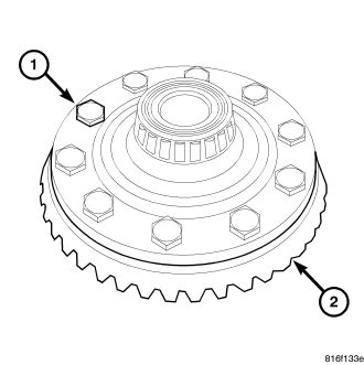
NOTE: The ring and pinion gears are serviced as a matched set. Never replace one gear without replacing the other gear.
1. Remove differential assembly from axle housing.
2. Remove ring gear bolts (1) and remove ring gear (2) from differential case.
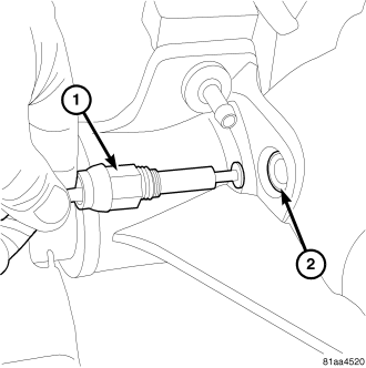
3. Remove Tru-Lok indicator switch (1) from differential housing (2).
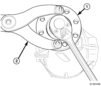
4. Hold pinion flange (1) with Flange Wrench C-3281 (2) and remove pinion nut.
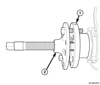
5. Remove pinion flange (1) with Puller C-452 (2).
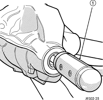
6. Remove pinion gear from housing with dead blow hammer (1).
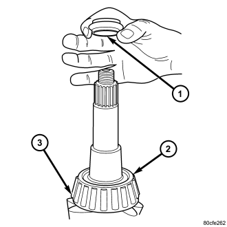
7. Remove collapsible spacer (1) from pinion gear (3).
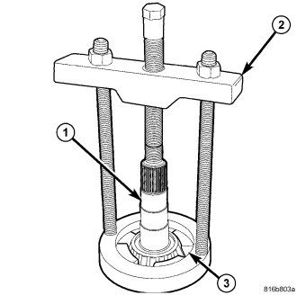
8. Remove rear pinion bearing from pinion shaft (1) with Puller C-293-PA (2) and Adapters C-293-47 (3).
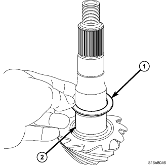
9. Remove pinion depth shim (1) from pinion shaft (2) and record thickness.
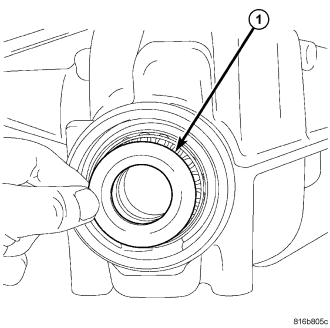
10. Remove pinion seal with seal puller.
11. Remove front bearing oil slinger (1).
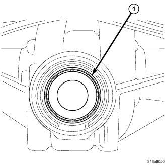
12. Remove front pinion bearing (1).
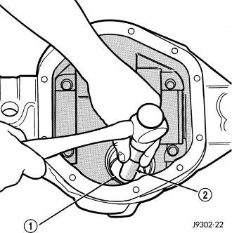
13. Remove front pinion bearing cup with Remover D-158 (1) and Handle C-4171 (2).
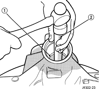
14. Remove rear bearing cup (1) and oil baffle with a hammer and punch (2).
INSTALLATION
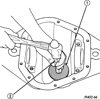
1. Install oil baffle in rear pinion cup bore.
2. Install rear pinion bearing cup with Installer C-4308 (1) and Handle C-4171 (2).
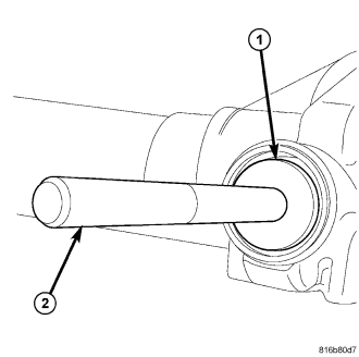
3. Install front pinion bearing cup with Installer D-146 (1) and Handle C-4171 (2).
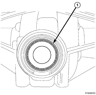
4. Install pinion front bearing (1).
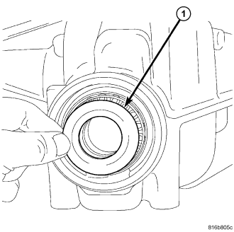
5. Install pinion front bearing oil slinger (1).
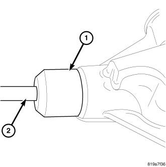
6. Apply a light coating of gear lubricant on pinion seal lip. Install seal with Installer 8681 (1) and Handle C-4171 (2).
7. Install pinion depth shim (1) on pinion gear shaft (2).
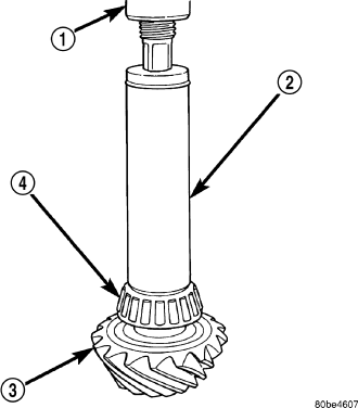
8. Install rear pinion bearing (4) on the pinion gear (3) with Installer C-4040 (2) and a press (1).
9. Install collapsible spacer (1) on pinion gear (3).
10. Install pinion gear in housing.
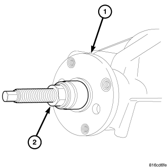
11. Install pinion flange (1) with Installer 8112 (2) and Cup 8109.
12. Install new nut on the pinion gear. Hold pinion flange (1) with Flange Wrench C-3281 (2) and tighten nut to 217 N·m (160 ft. lbs.).
13. Set torque wrench to 271 N·m (200 ft. lbs.) and tighten pinion nut in 6.8 N·m (5 ft. lbs.) increments until Pinion Torque To Rotate (PTTR) specification is achieved.
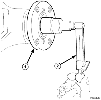
14. Measure Pinion Torque To Rotate (1) after each 6.8 N·m (5 ft. lbs.) increment with an inch pound torque wrench (2).
Pinion Torque To Rotate is:
- Original Bearings: 1 - 2 N·m (10 - 20 in. lbs.)
- New Bearings: 2 - 4.5 N·m (20 - 40 in. lbs.)
15. Install ring gear with new ring gear (2) bolts (1) and alternately tighten to 136 N·m (100 ft. lbs.).
CAUTION: Never reuse the ring gear bolts. Failure to follow these instruction may result in damage.
16. Install Tru-Lok indicator switch (1) into differential housing (2).
17. Install differential case into axle housing.
18. Measure differential Total Torque To Rotate (TTTR) with an inch pound torque wrench (2) before installing the axle shaft. This will verify differential bearing preload.
Total Torque To Rotate is: Pinion Torque To Rotate plus 0.79 - 1.24 N·m (7 - 11 in lbs.).
NOTE: If TTTR is too high, decrease shim thickness equally from both sides of the differential and check TTTR again. If TTTR is too low, increase shim thickness equally to both sides of the differential and check TTTR again.