PLUG - GLOW 2.8L DIESEL
DESCRIPTION
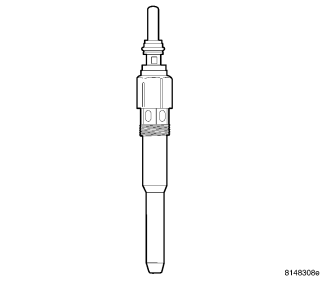
CAUTION: The glow plugs operate on a 7–volt system. The glow plugs DO NOT tolerate any over voltage. Full battery voltage will destroy the glow plug immediately. DO NOT test the glow plugs with a 12V source as damage will occur to the glow plug.
CAUTION:
CAUTION: Disregarding these instructions may cause severe engine damage.
Glow plugs are used to help start a cold or cool engine. The glow plugs will heat up and glow to heat the combustion chamber of each cylinder. An individual glow plug is used for each cylinder.
OPERATION
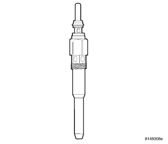
CAUTION: The glow plugs operate on a 7–volt system. DO NOT test the glow plugs with a 12 V source as damage will occur to the glow plug(s).
The Engine Control Module (ECM) monitors various engine sensors. When the ignition key is turned to the ON position, the ECM sends a signal to the glow plug module (relay) to turn on, and cycle, the glow plugs for a pre-determined amount of time, plus illuminate the glow plug light in the instrument panel. Once activated, the element inside of the ceramic core of the glow plug begins to glow. Each glow plug draws approximately 8 amps, for a total system amperage of 32 amps at 22° C (72° F) ambient temperature. If there is a fault with the glow plug system, the ECM will store a fault code.
DIAGNOSIS AND TESTING - GLOW PLUGS
CAUTION: DO NOT start the engine before the glow system tests correctly.
1. Measure the electrical resistance of the glow plug in the installed condition. Resistance should be less than 0.8Ω. The ground contact must be as close as possible to the glow plug contact to avoid introducing errors into the measurement.
2. If the resistance is out of tolerance, remove the glow plug and check it again separately.
3. Use the actuator test function for the glow plug module and glow plug lamp. The design and function of the glow plug module tests each glow plug to check the complete glow system.
4. If MIL is OFF and OBD has not recognized a malfunction of the glow system, testing is finished and the engine can be started.
5. If MIL is still ON, check the electrical connectors of glow plugs and power up the glow plugs again.
REMOVAL
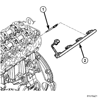
The four glow plugs (1) are attached to cylinder head below fuel rail.
1. Disconnect negative battery cable.
2. Remove fuel rail and high-pressure fuel lines.
3. Disconnect glow plug wiring harness (2) at all four glow plugs (1).
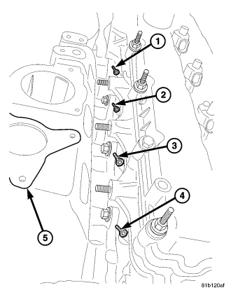
4. Use a socket to loosen glow plug(s) (1), (2), (3) or (4). After loosening, attach a flexible tool such as a rubber hose to remove glow plug from cylinder head.
CAUTION: After plug removal, do not bend, knock, or drop the glow plugs while handling (any mechanical impact may damage the glow plug).
5. Compare the removed glow plug with a new one. If parts of the ceramic heating element are missing, remove all fragments from the combustion chamber before you start the engine. The cylinder head must be removed to gain access to this missing ceramic material.
INSTALLATION
1. Attach a flexible tool such as a rubber hose to install glow plug into cylinder head, then tighten each plug to 14 N·m (10 ft. lbs.) (124 in. lbs.) torque.
2. Connect glow plug wiring harness (2) to all four glow plugs (1).
3. Install fuel rail and high-pressure fuel lines.
4. Connect negative battery cable.