DIAGNOSIS AND TESTING
- B123F-MENU SWITCH STUCK
- B127A-COMPASS PERFORMANCE
- B1288-TRIP/TOGGLE SWITCH PERFORMANCE
- B1613-PANEL ILLUMINATION CONTROL CIRCUIT LOW
- B1615-PANEL ILLUMINATION CONTROL CIRCUIT OPEN
- B210E-BATTERY VOLTAGE HIGH
- U0141-LOST COMMUNICATION WITH FRONT CONTROL MODULE (TOTALLY INTEGRATED POWER MODULE)
- U0161-LOST COMMUNICATION WITH COMPASS MODULE
- U0184-LOST COMMUNICATION WITH RADIO
- U1008-LIN 1 BUS
- U113B-LOST COMMUNICATION WITH SWITCH BANK MODULE
- U1149-LOST COMMUNICATION WITH MULTIFUNCTION SWITCH (STEERING CONTROL MODULE)
B123F-MENU SWITCH STUCK
For a complete wiring diagram Refer to Section 8W.
- When Monitored:
With the ignition on.
- Set Condition:
The Instrument Cluster detects the Menu Switch active for greater than 20 seconds.
| Possible Causes |
| INSTRUMENT CLUSTER |
Diagnostic Test
1. CHECK FOR AN ACTIVE DTCTurn the ignition on.
With the scan tool, record and erase DTCs.
Press the MENU switch three times.
With the scan tool, read DTCs.
Does the scan tool display this DTC as active?
Yes
- Replace the Instrument Cluster in accordance with the service information.
- Perform BODY VERIFICATION TEST - VER 1. (Refer to 8 - ELECTRICAL/ELECTRONIC CONTROL MODULES - STANDARD PROCEDURE)
No
- Test complete
B127A-COMPASS PERFORMANCE
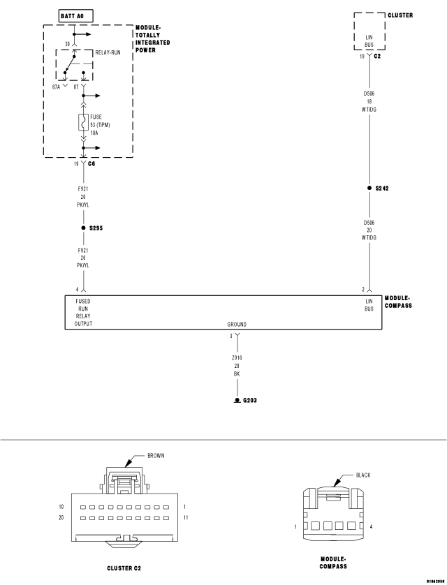
For a complete wiring diagram Refer to Section 8W.
- When Monitored:
With the ignition on.
- Set Condition:
Compass performance.
| Possible Causes |
| (F921) FUSED RUN RELAY OUTPUT CIRCUIT OPEN |
| (Z916) GROUND CIRCUIT OPEN |
| COMPASS MODULE |
| CLUSTER |
Diagnostic Test
1. CHECK FOR AN ACTIVE DTCNOTE: Remove any electronic devices (laptop computers, cell phones) from the instrument panel.
NOTE: Before proceeding, check the compass variance and calibration in accordance with the service information.
Turn the ignition on.
With the scan tool, record and erase DTCs.
Wait 30 seconds.
With the scan tool, read DTCs.
Does the scan tool display this DTC as active?
Yes
- Go To 2
No
- The condition that caused this code to set is not present at this time. Check for an intermittent condition by inspecting the related wiring harness for chafed, pierced, pinched, and partially broken wires. Also inspect the related connectors for broken, bent, pushed out, spread, corroded, or contaminated terminals.
- Perform BODY VERIFICATION TEST - VER 1. (Refer to 8 - ELECTRICAL/ELECTRONIC CONTROL MODULES - STANDARD PROCEDURE)
2. (F921) FUSED RUN RELAY OUTPUT CIRCUIT OPEN
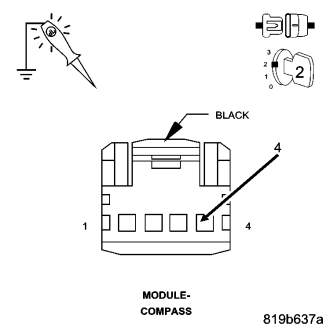
Measure the voltage of the (F921) Fused Run Relay Output circuit for an open.
Is the voltage above 10 volts?
Yes
- Go To 3
No
- Repair the (F921) Fused Run Relay Output circuit for an open.
- Perform BODY VERIFICATION TEST - VER 1. (Refer to 8 - ELECTRICAL/ELECTRONIC CONTROL MODULES - STANDARD PROCEDURE)
3. (Z916) GROUND CIRCUIT OPEN
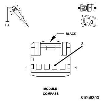
Measure the resistance of the (Z916) Ground circuit for an open.
Is the resistance above 10K ohms?
Yes
- Repair the (Z916) Ground circuit for an open.
- Perform BODY VERIFICATION TEST - VER 1. (Refer to 8 - ELECTRICAL/ELECTRONIC CONTROL MODULES - STANDARD PROCEDURE)
No
- Replace the Compass Module in accordance with the service information.
- Perform BODY VERIFICATION TEST - VER 1. (Refer to 8 - ELECTRICAL/ELECTRONIC CONTROL MODULES - STANDARD PROCEDURE)
B1288-TRIP/TOGGLE SWITCH PERFORMANCE
For a complete wiring diagram Refer to Section 8W.
- When Monitored:
With the ignition on.
- Set Condition:
The Instrument Cluster detects the Trip/Toggle Switch active for greater than 20 seconds.
| Possible Causes |
| INSTRUMENT CLUSTER |
Diagnostic Test
1. CHECK FOR AN ACTIVE DTCTurn the ignition on.
With the scan tool, record and erase DTCs.
Press the Trip/Toggle switch three times.
With the scan tool, read DTCs.
Does the scan tool display this DTC as active?
Yes
- Replace the Instrument Cluster in accordance with the service information.
- Perform BODY VERIFICATION TEST - VER 1. (Refer to 8 - ELECTRICAL/ELECTRONIC CONTROL MODULES - STANDARD PROCEDURE)
No
- Test complete
B1613-PANEL ILLUMINATION CONTROL CIRCUIT LOW
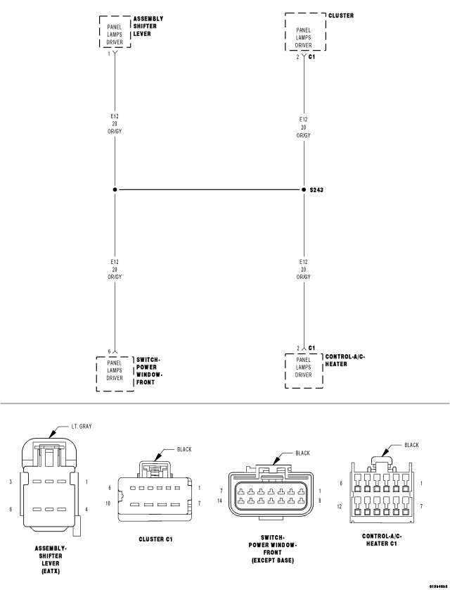
For a complete wiring diagram Refer to Section 8W.
- When Monitored:
With the ignition on and the Panel Illumination active.
- Set Condition:
Panel Illumination Status LOW.
| Possible Causes |
| (E12) PANEL LAMPS DRIVER CIRCUIT SHORTED TO GROUND |
| A/C HEATER CONTROL LAMP (FRONT AND/OR REAR) SHORTED TO GROUND |
| FRONT WINDOW SWITCH LAMP SHORTED TO GROUND |
| SHIFT ASSEMBLY LAMP SHORTED TO GROUND |
| CLUSTER |
Diagnostic Test
1. CHECK FOR AN ACTIVE DTCTurn the ignition on.
With the scan tool, record and erase DTCs.
Activate the Panel Illumination.
Wait 30 seconds.
With the scan tool, read DTCs.
Does the scan tool display this DTC as active?
Yes
- Go To 2
No
- The condition that caused this code to set is not present at this time. Check for an intermittent condition by inspecting the related wiring harness for chafed, pierced, pinched, and partially broken wires. Also inspect the related connectors for broken, bent, pushed out, spread, corroded, or contaminated terminals.
- Perform BODY VERIFICATION TEST - VER 1. (Refer to 8 - ELECTRICAL/ELECTRONIC CONTROL MODULES - STANDARD PROCEDURE)
2. CHECK EACH NON-FUNCTIONING COMPONENT FOR AN INTERNAL SHORT TO GROUND
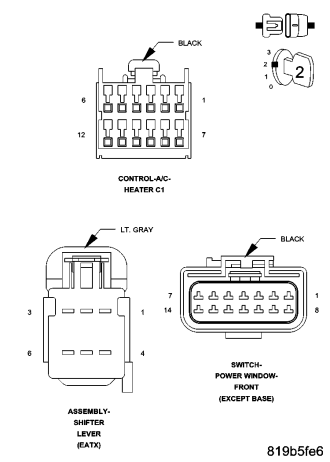
NOTE: Using the wiring diagram as a guide disconnect each non-functioning component one at a time while checking for the DTC to become stored. Repeat these steps for each component.
Turn the ignition off.
Disconnect the non-functioning component harness connector.
Turn the ignition on.
Activate the Panel Illumination.
With the scan tool, read DTCs.
Is the DTC still active?
Yes
- Go To 3
No
- Replace the non-functioning component that when disconnected caused the DTC to become stored in accordance with the service information.
- Perform BODY VERIFICATION TEST - VER 1. (Refer to 8 - ELECTRICAL/ELECTRONIC CONTROL MODULES - STANDARD PROCEDURE)
3. CHECK THE (E12) PANEL LAMPS DRIVER CIRCUIT FOR A SHORT TO GROUND
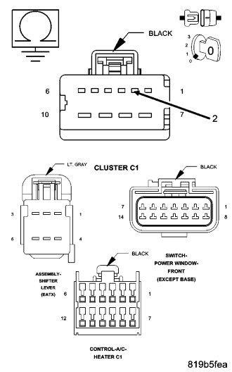
Turn the ignition off.
Disconnect the Instrument Cluster C1 harness connector.
With all (E12) Panel Lamps Driver circuit components disconnected, measure the resistance to ground on the (E12) Panel Lamps Driver Circuit from the Instrument Cluster C1 harness connector.
Is the resistance less than 10K ohms?
Yes
- Repair the (E12) Panel Lamps Driver circuit for a short to ground.
- Perform BODY VERIFICATION TEST - VER 1. (Refer to 8 - ELECTRICAL/ELECTRONIC CONTROL MODULES - STANDARD PROCEDURE)
No
- Replace the Cluster in accordance with the service information.
- Perform BODY VERIFICATION TEST - VER 1. (Refer to 8 - ELECTRICAL/ELECTRONIC CONTROL MODULES - STANDARD PROCEDURE)
B1615-PANEL ILLUMINATION CONTROL CIRCUIT OPEN
For a complete wiring diagram Refer to Section 8W.
- When Monitored:
With the ignition on and the Panel Illumination circuit active.
- Set Condition:
The Instrument Cluster detects an open condition on the Panel Illumination Control circuit.
| Possible Causes |
| (E12) PANEL LAMPS DRIVER CIRCUIT OPEN |
| INSTRUMENT CLUSTER |
Diagnostic Test
1. CHECK FOR AN ACTIVE DTCTurn the ignition on.
With the scan tool, record and erase DTCs.
Activate the Panel Illumination.
Wait 30 seconds.
With the scan tool, read DTCs.
Does the scan tool display this DTC as active?
Yes
- Go To 2
No
- The condition that caused this code to set is not present at this time. Check for an intermittent condition by inspecting the related wiring harness for chafed, pierced, pinched, and partially broken wires. Also inspect the related connectors for broken, bent, pushed out, spread, corroded, or contaminated terminals.
- Perform BODY VERIFICATION TEST - VER 1. (Refer to 8 - ELECTRICAL/ELECTRONIC CONTROL MODULES - STANDARD PROCEDURE)
2. CHECK THE (E12) PANEL LAMPS DRIVER CIRCUIT FOR AN OPEN
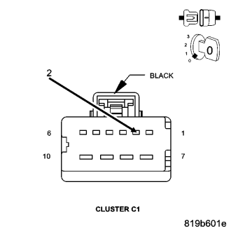
Turn the ignition off.
Disconnect the Cluster C1 harness connector.
Inspect the connector and associated wiring for the Panel illumination circuit.
Using a fused jumper wire connected to 12 volts, probe cavity 2 of the Cluster C1 harness connector.
Did the components illuminate?
Yes
- Replace the Instrument Cluster in accordance with the service information.
- Perform BODY VERIFICATION TEST - VER 1. (Refer to 8 - ELECTRICAL/ELECTRONIC CONTROL MODULES - STANDARD PROCEDURE)
No
- Using the wiring diagrams as a guide, locate and repair the (E12) Panel Lamps Driver circuit for an open.
- Perform BODY VERIFICATION TEST - VER 1. (Refer to 8 - ELECTRICAL/ELECTRONIC CONTROL MODULES - STANDARD PROCEDURE)
B210E-BATTERY VOLTAGE HIGH
For a complete wiring diagram Refer to Section 8W.
- When Monitored:
With the ignition on.
- Set Condition:
Battery voltage greater than 16 volts for approximately 15 seconds.
| Possible Causes |
| GENERATOR |
| PCM |
Diagnostic Test
1. CHECK FOR ANY POWERTRAIN CONTROL MODULES DTCSNOTE: Make sure the Battery is in good condition. Using the Midtronics Battery Tester, test the Battery before continuing.
NOTE: Inspect the vehicle for after market accessories that may exceed the Generator System output.
NOTE: Make sure the generator drive belt is in good operating condition.
NOTE: Inspect the fuses in the TIPM. If an open fuse is found, use the wire diagram/schematic as a guide, inspect the wiring and connectors for damage.
Turn the ignition on.
With the scan tool, read active PCM DTC's.
Does the scan tool display any active PCM DTC's?
Yes
- (Refer to 9 - ENGINE - DIAGNOSIS AND TESTING) for the diagnostic test procedure.
No
- Check the above conditions that can cause a high voltage condition. Repair as necessary.
- Perform BODY VERIFICATION TEST – VER 1. (Refer to 8 - ELECTRICAL/ELECTRONIC CONTROL MODULES - STANDARD PROCEDURE)
U0141-LOST COMMUNICATION WITH FRONT CONTROL MODULE (TOTALLY INTEGRATED POWER MODULE)
For a complete wiring diagram Refer to Section 8W.
(Refer to 8 - ELECTRICAL/ELECTRONIC CONTROL MODULES - DIAGNOSIS AND TESTING) for the diagnostic test procedure.
U0161-LOST COMMUNICATION WITH COMPASS MODULE
For a complete wiring diagram Refer to Section 8W.
- When Monitored:
With the ignition on.
- Set Condition:
The Cluster does not receive information from the Compass Module.
| Possible Causes |
| (D506) LIN BUS CIRCUIT OPEN |
| (F921) FUSED IGNITION SWITCH OUTPUT (RUN) CIRCUIT OPEN |
| (Z916) GROUND CIRCUIT OPEN |
| COMPASS MODULE |
| INSTRUMENT CLUSTER |
Diagnostic Test
1. CHECK FOR AN ACTIVE DTCNOTE: Remove any electronic devices (laptop computers, cell phones) from the instrument panel.
NOTE: Before proceeding, check the compass variance and calibration in accordance with the service information.
Turn the ignition on.
With the scan tool, record and erase DTCs.
Wait 30 seconds.
With the scan tool, read DTCs.
Does the scan tool display this DTC as active?
Yes
- Go To 2
No
- The condition that caused this code to set is not present at this time. Check for an intermittent condition by inspecting the related wiring harness for chafed, pierced, pinched, and partially broken wires. Also inspect the related connectors for broken, bent, pushed out, spread, corroded, or contaminated terminals.
- Perform BODY VERIFICATION TEST - VER 1. (Refer to 8 - ELECTRICAL/ELECTRONIC CONTROL MODULES - STANDARD PROCEDURE)
2. (D506) LIN BUS CIRCUIT
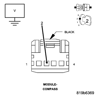
Turn the ignition off.
Disconnect the Compass Module harness connector.
Turn the ignition on.
Measure the voltage of the (D506) LIN BUS circuit.
Is the voltage above 5 volts?
Yes
- Go To 4
No
- Go To 3
3. (D506) LIN BUS CIRCUIT OPEN
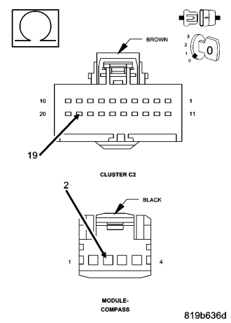
Turn the ignition off.
Disconnect the Instrument Cluster C2 harness connector.
Measure the resistance of the (D506) LIN BUS circuit.
Is the resistance below 10K ohms?
Yes
- Replace the Cluster in accordance with the service information.
- Perform BODY VERIFICATION TEST - VER 1. (Refer to 8 - ELECTRICAL/ELECTRONIC CONTROL MODULES - STANDARD PROCEDURE)
No
- Repair the (D506) LIN BUS circuit for an open.
- Perform BODY VERIFICATION TEST - VER 1. (Refer to 8 - ELECTRICAL/ELECTRONIC CONTROL MODULES - STANDARD PROCEDURE)
4. (F921) FUSED IGNITION SWITCH OUTPUT (RUN) CIRCUIT OPEN
Turn the ignition on.
Using a 12-volt test light connected to ground, check the (F921) Fused Ignition Switch Output (RUN) circuit at the Compass Module harness connector.
Does the test light illuminate brightly?
Yes
- Go To 5
No
- Repair the (F921) Fused Ignition Switch Output (RUN) circuit for an open.
- Perform BODY VERIFICATION TEST - VER 1. (Refer to 8 - ELECTRICAL/ELECTRONIC CONTROL MODULES - STANDARD PROCEDURE)
5. (Z916) GROUND CIRCUIT OPEN
Turn the ignition off.
Using a 12-volt test light connected to 12-volts, check the (Z916) Ground circuit at the Compass Module harness connector.
Does the test light illuminate brightly?
Yes
- Replace the Compass Module in accordance with the service information.
- Perform BODY VERIFICATION TEST - VER 1. (Refer to 8 - ELECTRICAL/ELECTRONIC CONTROL MODULES - STANDARD PROCEDURE)
No
- Repair the (Z916) ground circuit for an open.
- Perform BODY VERIFICATION TEST - VER 1. (Refer to 8 - ELECTRICAL/ELECTRONIC CONTROL MODULES - STANDARD PROCEDURE)
U0184-LOST COMMUNICATION WITH RADIO
For a complete wiring diagram Refer to Section 8W.
(Refer to 8 - ELECTRICAL/ELECTRONIC CONTROL MODULES - DIAGNOSIS AND TESTING) for the diagnostic test procedure.
U1008-LIN 1 BUS
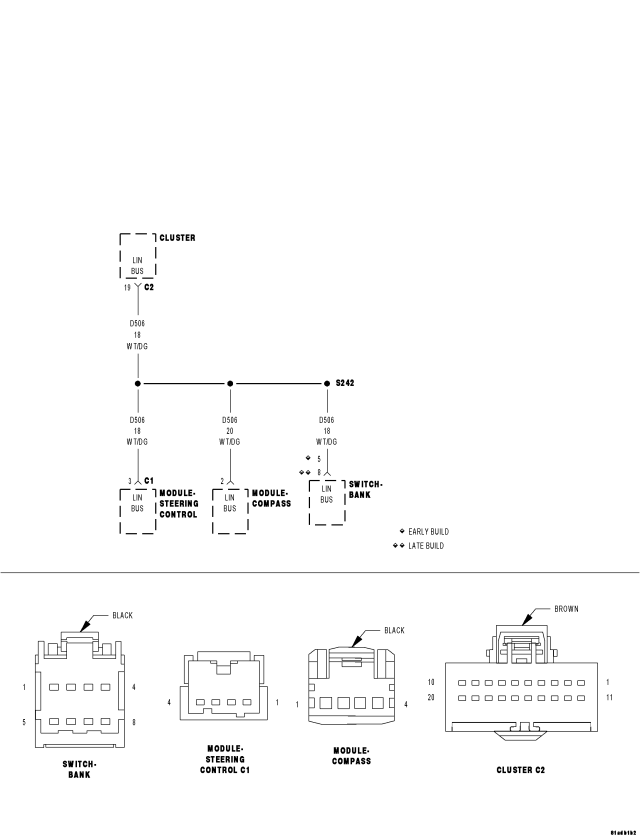
For a complete wiring diagram Refer to Section 8W.
- When Monitored:
With the ignition on.
- Set Condition:
LIN 1 Bus Performance.
| Possible Causes |
| (D506) LIN BUS CIRCUIT OPEN |
| (D506) LIN BUS CIRCUIT SHORT TO GROUND |
| CLUSTER |
Diagnostic Test
1. CHECK FOR AN ACTIVE DTCTurn the ignition on.
With the scan tool, record and erase DTCs.
Wait 30 seconds.
With the scan tool, read DTCs.
Does the scan tool display: U1008–LIN 1 BUS?
Yes
- Go To 2
No
- The condition that caused this code to set is not present at this time. Check for an intermittent condition by inspecting the related wiring harness for chafed, pierced, pinched, and partially broken wires. Also inspect the related connectors for broken, bent, pushed out, spread, corroded, or contaminated terminals.
- Perform BODY VERIFICATION TEST - VER 1. (Refer to 8 - ELECTRICAL/ELECTRONIC CONTROL MODULES - STANDARD PROCEDURE)
2. SHORTED COMPONENT
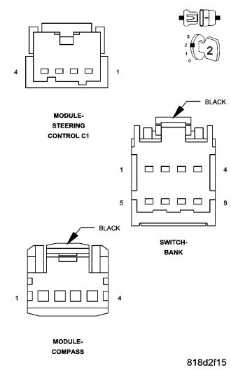
NOTE: After disconnecting each component, check DTCs with the scan tool.
Turn the ignition on.
Disconnect the Compass Module harness connector.
Disconnect the Switch Bank harness connector.
Disconnect the Steering Control Module C1 harness connector.
With each component disconnected, did the DTC U1008–LIN 1 BUS change from active to stored?
Yes
- Replace the component that caused the DTC U1008–LIN 1 BUS to change from active to stored.
- Perform BODY VERIFICATION TEST - VER 1. (Refer to 8 - ELECTRICAL/ELECTRONIC CONTROL MODULES - STANDARD PROCEDURE)
No
- Go To3
3. (D506) LIN BUS CIRCUIT OPEN
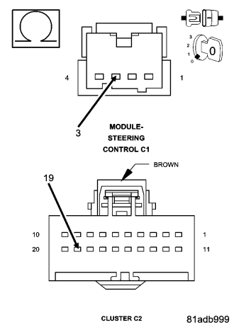
Turn the ignition off.
Disconnect the Cluster C2 harness connector.
Disconnect the Multifunction Switch harness connector.
Measure the resistance of the (D506) LIN Bus circuit.
Is the resistance above 10K ohms?
Yes
- Repair the (D506) LIN Bus circuit for an open.
- Perform BODY VERIFICATION TEST - VER 1. (Refer to 8 - ELECTRICAL/ELECTRONIC CONTROL MODULES - STANDARD PROCEDURE)
No
- Go To4
4. (D506) LIN BUS CIRCUIT SHORT TO GROUND
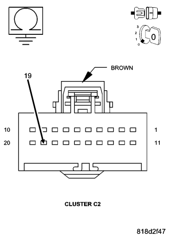
Turn the ignition off.
Measure the resistance to ground on the (D506) LIN Bus circuit.
Is the resistance below 10K ohms?
Yes
- Repair the (D506) LIN Bus circuit for a short to ground.
- Perform BODY VERIFICATION TEST - VER 1. (Refer to 8 - ELECTRICAL/ELECTRONIC CONTROL MODULES - STANDARD PROCEDURE)
No
- Replace the Cluster in accordance with the service information.
- Perform BODY VERIFICATION TEST - VER 1. (Refer to 8 - ELECTRICAL/ELECTRONIC CONTROL MODULES - STANDARD PROCEDURE)
U113B-LOST COMMUNICATION WITH SWITCH BANK MODULE
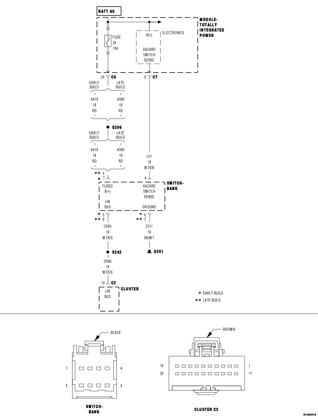
For a complete wiring diagram Refer to Section 8W.
- When Monitored:
With the ignition on.
- Set Condition:
The Cluster does not receive information from the Switch Bank Module.
| Possible Causes |
| (D506) LIN BUS CIRCUIT OPEN |
| (A418) FUSED B+ CIRCUIT (EARLY PRODUCTION) OPEN |
| (A909) FUSED B+ CIRCUIT (LATE PRODUCTION) OPEN |
| (Z911) GROUND CIRCUIT OPEN |
| SWITCH BANK MODULE |
| CLUSTER |
Diagnostic Test
1. CHECK FOR AN ACTIVE DTCTurn the ignition on.
With the scan tool, record and erase DTCs.
Wait 30 seconds.
With the scan tool, read DTCs.
Does the scan tool display this DTC as active?
Yes
- Go To 2
No
- The condition that caused this code to set is not present at this time. Check for an intermittent condition by inspecting the related wiring harness for chafed, pierced, pinched, and partially broken wires. Also inspect the related connectors for broken, bent, pushed out, spread, corroded, or contaminated terminals.
- Perform BODY VERIFICATION TEST - VER 1. (Refer to 8 - ELECTRICAL/ELECTRONIC CONTROL MODULES - STANDARD PROCEDURE)
2. (D506) LIN BUS CIRCUIT
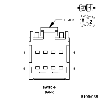
Turn the ignition off.
Disconnect the Switch Bank Module harness connector.
Turn the ignition on.
Measure the voltage of the (D506) LIN BUS circuit.
Is the voltage above 5 volts?
Yes
- Go To 4
No
- Go To 3
3. (D506) LIN BUS CIRCUIT OPEN
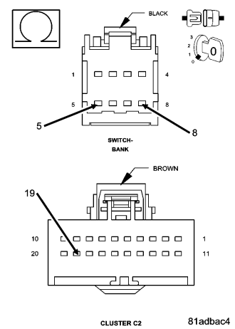
Turn the ignition off.
Disconnect the Cluster C2 harness connector.
Measure the resistance of the (D506) LIN BUS circuit.
Is the resistance below 10K ohms?
Yes
- Replace the Cluster in accordance with the service information.
- Perform BODY VERIFICATION TEST - VER 1. (Refer to 8 - ELECTRICAL/ELECTRONIC CONTROL MODULES - STANDARD PROCEDURE)
No
- Repair the (D506) LIN BUS circuit for an open.
- Perform BODY VERIFICATION TEST - VER 1. (Refer to 8 - ELECTRICAL/ELECTRONIC CONTROL MODULES - STANDARD PROCEDURE)
4. (A418)/(A909) FUSED B+ CIRCUIT OPEN
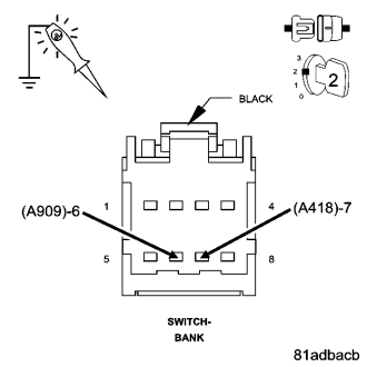
Turn the ignition on.
Using a 12-volt test light connected to ground, check the (A418)/(A909) Fused B+ circuit at the Switch Bank Module harness connector.
Does the test light illuminate brightly?
Yes
- Go To 5
No
- Repair the (A418)/(A909) Fused B+ circuit for an open.
- Perform BODY VERIFICATION TEST - VER 1. (Refer to 8 - ELECTRICAL/ELECTRONIC CONTROL MODULES - STANDARD PROCEDURE)
5. (Z911) GROUND CIRCUIT OPEN
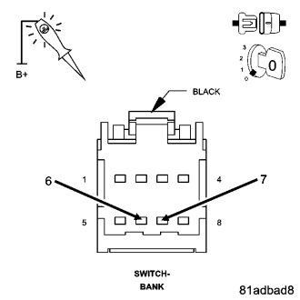
Turn the ignition off.
Using a 12-volt test light connected to 12-volts, check the (Z911) Ground circuit at the Switch Bank Module harness connector.
Does the test light illuminate brightly?
Yes
- Replace the Switch Bank Module in accordance with the service information.
- Perform BODY VERIFICATION TEST - VER 1. (Refer to 8 - ELECTRICAL/ELECTRONIC CONTROL MODULES - STANDARD PROCEDURE)
No
- Repair the (Z911) ground circuit for an open.
- Perform BODY VERIFICATION TEST - VER 1. (Refer to 8 - ELECTRICAL/ELECTRONIC CONTROL MODULES - STANDARD PROCEDURE)
U1149-LOST COMMUNICATION WITH MULTIFUNCTION SWITCH (STEERING CONTROL MODULE)
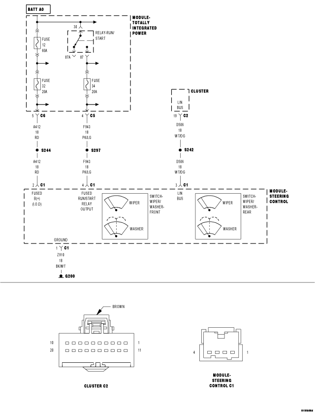
For a complete wiring diagram Refer to Section 8W.
- When Monitored:
With the ignition on.
- Set Condition:
The Cluster does not receive information from the Steering Control Module.
| Possible Causes |
| (D506) LIN BUS CIRCUIT OPEN |
| (F943) FUSED RUN/START RELAY OUTPUT CIRCUIT OPEN |
| (A412) FUSED B(+) (I.O.D.) CIRCUIT OPEN |
| (Z910) GROUND CIRCUIT OPEN |
| STEERING CONTROL MODULE |
| CLUSTER |
Diagnostic Test
1. CHECK FOR AN ACTIVE DTCTurn the ignition on.
With the scan tool, record and erase DTCs.
Wait 30 seconds.
With the scan tool, read DTCs.
Does the scan tool display this DTC as active?
Yes
- Go To 2
No
- The condition that caused this code to set is not present at this time. Check for an intermittent condition by inspecting the related wiring harness for chafed, pierced, pinched, and partially broken wires. Also inspect the related connectors for broken, bent, pushed out, spread, corroded, or contaminated terminals.
- Perform BODY VERIFICATION TEST - VER 1. (Refer to 8 - ELECTRICAL/ELECTRONIC CONTROL MODULES - STANDARD PROCEDURE)
2. (D506) LIN BUS CIRCUIT
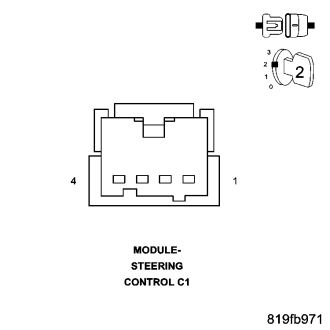
Turn the ignition off.
Disconnect the Steering Control Module harness connector.
Turn the ignition on.
Measure the voltage of the (D506) LIN BUS circuit.
Is the voltage above 5 volts?
Yes
- Go To 4
No
- Go To 3
3. (D506) LIN BUS CIRCUIT OPEN
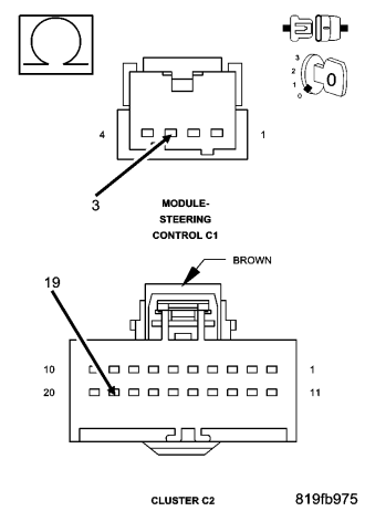
Turn the ignition off.
Disconnect the Cluster C2 harness connector.
Measure the resistance of the (D506) LIN BUS circuit.
Is the resistance below 10K ohms?
Yes
- Replace the Cluster in accordance with the service information.
- Perform BODY VERIFICATION TEST - VER 1. (Refer to 8 - ELECTRICAL/ELECTRONIC CONTROL MODULES - STANDARD PROCEDURE)
No
- Repair the (D506) LIN BUS circuit for an open.
- Perform BODY VERIFICATION TEST - VER 1. (Refer to 8 - ELECTRICAL/ELECTRONIC CONTROL MODULES - STANDARD PROCEDURE)
4. (F943) FUSED RUN/START RELAY OUTPUT CIRCUIT OPEN
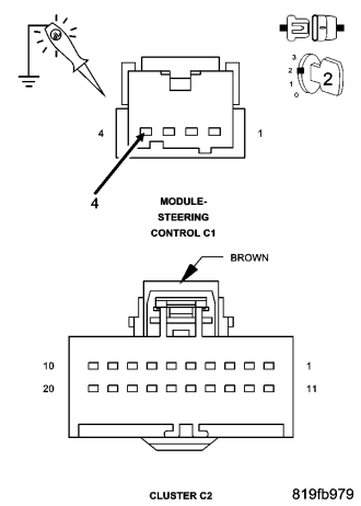
Turn the ignition on.
Using a 12-volt test light connected to ground, check the (F943) Fused RUN/START Relay Output circuit at the Steering Control Module harness connector.
Does the test light illuminate brightly?
Yes
- Go To 5
No
- Repair the (F943) Fused RUN/START Relay Output circuit for an open.
- Perform BODY VERIFICATION TEST - VER 1. (Refer to 8 - ELECTRICAL/ELECTRONIC CONTROL MODULES - STANDARD PROCEDURE)
5. (A412) FUSED B(+) (I.O.D.) CIRCUIT OPEN
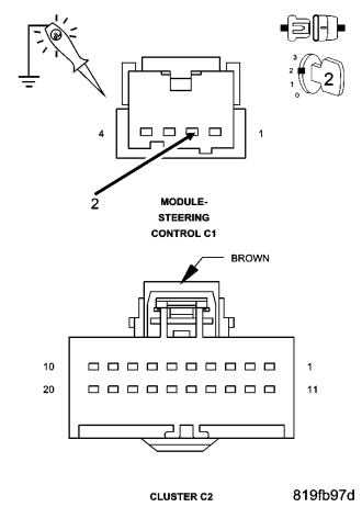
Turn the ignition on.
Using a 12-volt test light connected to ground, check the (A412) Fused B+ (I.O.D.) circuit at the Steering Control Module harness connector.
Does the test light illuminate brightly?
Yes
- Go To 6
No
- Repair the (A412) Fused B+ (I.O.D.) circuit for an open.
- Perform BODY VERIFICATION TEST - VER 1. (Refer to 8 - ELECTRICAL/ELECTRONIC CONTROL MODULES - STANDARD PROCEDURE)
6. (Z910) GROUND CIRCUIT OPEN
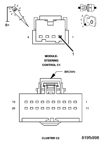
Turn the ignition off.
Using a 12-volt test light connected to 12-volts, check the (Z910) Ground circuit at the Steering Control Module harness connector.
Does the test light illuminate brightly?
Yes
- Replace the Steering Control Module in accordance with the service information.
- Perform BODY VERIFICATION TEST - VER 1. (Refer to 8 - ELECTRICAL/ELECTRONIC CONTROL MODULES - STANDARD PROCEDURE)
No
- Repair the (Z916) ground circuit for an open.
- Perform BODY VERIFICATION TEST - VER 1. (Refer to 8 - ELECTRICAL/ELECTRONIC CONTROL MODULES - STANDARD PROCEDURE)