HEADLAMP LEVELING MOTOR
DESCRIPTION
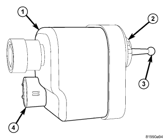
The headlamp leveling motor (1) is located on the engine compartment side of the front end module carrier behind each headlamp unit on vehicles equipped with the headlamp leveling system, which is available only in certain markets where it is required equipment. The motor is encased within a molded plastic housing and is secured by an integral wedge-type mounting boss (2) to a keyed flange on the front end module carrier.
The outside of the motor housing features an integral molded connector (4) on its lower rearward surface and a plastic pushrod with a ball formation (3) on its free end extends from the motor mounting boss. Within the motor housing is a 12-volt Direct Current (DC) servo motor, an electronic controller board that includes the motor logic circuits, and an integral screw-drive transmission. The headlamp leveling motor is connected to the vehicle electrical system through a dedicated take out and connector of the headlamp wire harness.
The motor cannot be repaired and, if ineffective or damaged, it must be replaced.
OPERATION
The controller board and logic circuitry of the headlamp leveling motor control motor operation based upon a voltage signal input received from the Totally Integrated Power Module (TIPM). The TIPM uses electronic messages received over the Controller Area Network (CAN) data bus from the ElectroMechanical Instrument Cluster (EMIC) (also known as the Cab Compartment Node/CCN) to determine the correct voltage signal to provide the leveling motor, while the EMIC uses electronic messages received over the Local Interface Network (LIN) data bus from the instrument panel switch pod to monitor the headlamp leveling switch selection.
The headlamp leveling motors have a path to ground at all times. The headlamp leveling motors operate on battery voltage received through the headlamp low beam feed circuits so that the system will only operate when the headlamp low beams are turned ON. When the motor is energized it will extend or retract the motor pushrod through an integral screw-drive transmission. The ball on the end of the pushrod is snapped into a socket on one end of a molded plastic spacer. The other end of the spacer snaps into a receptacle in the molded plastic headlamp mounting collar for the headlamp unit on the face of the front end module carrier. The headlamp then moves vertically as the pushrod is extended or retracted, changing the angle at which light is projected from the headlamps.
The hard wired circuits for the headlamp leveling motors may be diagnosed using conventional diagnostic tools and procedures. Refer to the appropriate wiring information. However, conventional diagnostic methods will not prove conclusive in the diagnosis of the active electronic elements within the headlamp leveling motors or the electronic controls and communication between other modules and devices that provide some features of the headlamp leveling system. The most reliable, efficient, and accurate means to diagnose the headlamp leveling motor or the electronic controls and communication related to headlamp leveling system operation requires the use of a diagnostic scan tool. Refer to the appropriate diagnostic information.
REMOVAL
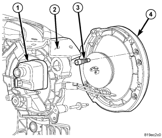
1. Disconnect and isolate the battery negative cable.
2. Disconnect the engine compartment wire harness connector from the headlamp leveling motor (1) connector receptacle.
3. Rotate the headlamp leveling motor on the back of the front end module carrier (2) counterclockwise about 30 degrees.
4. Grasp the motor firmly with one hand and pull sharply and quickly straight rearward to unsnap the ball on the end of the motor pushrod from the socket on the spacer (3).
5. Remove the headlamp leveling motor from the engine compartment.
NOTE: The spacer and the headlamp mounting collar (4) cannot be repaired. If the spacer or collar break or if the spacer becomes disengaged from the collar before the leveling motor pushrod disengages the spacer, both the spacer and the mounting collar will also require replacement.
INSTALLATION
1. Position the headlamp leveling motor (1) and pushrod to the mounting boss on the back of the front end module carrier (2).
2. Align the ball on the end of the leveling motor pushrod with the socket in the spacer (3).
3. While stabilizing the headlamp from the face of the front end module carrier with one hand, firmly and steadily push the headlamp leveling motor pushrod straight into the spacer to snap the ball on the pushrod into the socket end of the spacer.
4. Insert the mounting flange of the headlamp leveling motor into the mounting boss on the front end module carrier until the motor is firmly seated.
5. Rotate the headlamp leveling motor clockwise about 30 degrees to lock it into place.
6. Reconnect the engine compartment wire harness connector to the headlamp leveling motor connector receptacle.
7. Reconnect the battery negative cable.
NOTE: The spacer and the headlamp mounting collar (4) cannot be repaired. If the spacer or collar break or if the spacer becomes disengaged from the collar before the leveling motor pushrod engages the spacer, both the spacer and the mounting collar will also require replacement.