LAMPS/LIGHTING - EXTERIOR
DESCRIPTION
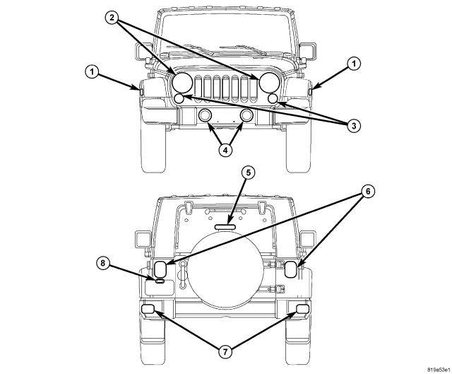
The exterior lighting system for this vehicle includes the following exterior lamp units:
- Center High Mounted Stop Lamp (5) - A standard equipment Center High Mounted Stop Lamp (CHMSL) is mounted to a stanchion that is integral to the spare tire carrier centered on the swing gate at the rear of the vehicle.
- Front Fog Lamps (4) - Optional equipment front fog lamp units are mounted inboard of the bumperettes of the front bumper on vehicles manufactured for domestic markets, or outboard of the bumperettes on vehicles manufactured for export markets.
- Front Park/Turn Lamps (3) - A standard equipment front park/turn lamp unit is mounted at each lower outboard corner of the grille panel.
- Front Position Lamps - A front position lamp is integral to each headlamp unit on vehicles manufactured for export markets where they are required.
- Front Side Marker or Repeater Lamps (1) - A standard equipment front side marker lamp is located near the front of each front fender flare on vehicles manufactured for domestic markets. The front side marker lamps are replaced with a standard repeater lamp mounted in the same location on vehicles manufactured for export markets where they are required.
- Headlamps (2) - A standard equipment front headlamp is mounted to the front end module support at each upper outboard corner of the grille panel.
- License Plate Lamps (8) - A single standard equipment rear license plate lamp unit is integral to the license plate mounting bracket just below the left rear lamp unit on vehicles manufactured for domestic markets. A bracket with two rear license plate lamps is located on the rear bumper directly below the spare tire on vehicles manufactured for export markets.
- Rear Fog Lamps (7) - Rear fog lamp units are mounted on the outboard ends of the rear bumpers on vehicles manufactured for export markets where they are required.
- Rear Lamp Units (6) - A standard equipment rear lamp unit is mounted to the rear of each rear body corner panel on either side of the swing gate opening.
- Underhood Lamp - Vehicles equipped with this option have a single underhood lamp unit with an integral automatic mechanical (non-mercury) switch. The lamp and switch unit is mounted to the underside of the inner hood reinforcement above the right side of the engine compartment.
These exterior lighting lamp units and their controls are combined to provide the following exterior lighting features:
- Backup Lamps - The backup (or reverse) lamps include a clear bulb, reflector and clear lens that are integral to each rear lamp unit.
- Brake Lamps - The brake (or stop) lamps include a clear bulb, reflector and red lens that are integral to each rear lamp unit, and the red lens and multiple Light-Emitting Diode (LED) units of the CHMSL.
- Daytime Running Lamps - Daytime Running Lamps (DRL) are standard equipment on vehicles manufactured for sale in Canada and optional on vehicles manufactured for the United States. Vehicles with DRL illuminate the high beam filament of each headlamp bulb at a reduced intensity to serve as the DRLs.
- Exterior Lamp Fail-Safe Operation - The ElectroMechanical Instrument Cluster (EMIC) (also known as the Cab Compartment Node/CCN) and the Totally Integrated Power Module (TIPM) provide a fail-safe feature which will automatically turn ON the low beam headlamps and all park lamps when the ignition switch is in the ON position and there is no detected input from the Steering Control Module (SCM), or when there is no communication over the Local Interface Network (LIN) or Controller Area Network (CAN) data buses.
- Exterior Lamp Load Shedding - The TIPM provides a battery saver feature which will automatically turn OFF all exterior lamps that remain ON with the ignition switch in the LOCK position after a timed interval of about eight minutes.
- Front Fog Lamps - The standard equipment front fog lamps include the clear bulb, reflector and clear lens of each adjustable front fog lamp unit.
- Hazard Warning Lamps - The hazard warning lamps include the bulbs, reflectors and lenses of each lamp in the right and left, front and rear turn signal circuits.
- Headlamp Delay - The standard equipment low or high beam headlamps remain illuminated for a customer-programmable delay period of 0 (disabled), 30, 60 or 90 seconds when the headlamps are turned OFF after the ignition switch has been turned to the OFF position.
- Headlamps - The headlamps include a single, dual filament halogen bulb, a reflector and a clear lens integral to each headlamp unit. Headlamps for domestic markets are vertically adjustable, while those for export markets are both vertically and horizontally adjustable.
- Headlamp Leveling - Headlamp leveling is available only in certain markets where it is required equipment. A headlamp leveling actuator motor attached to each headlamp mounting collar and a headlamp leveling switch integral to the switch pod in the instrument panel center stack allow the headlamp beam pattern to be adjusted by the vehicle operator from the interior of the vehicle to compensate for variable passenger or cargo loads.
- Optical Horn - Also known as flash-to-pass, the beam selection function of the left (lighting) multi-function switch control stalk has a momentary intermediate position that allows the headlamp high beams to be flashed momentarily, without changing the headlamp beam selection.
- Park Lamps - The front park lamps include the bulbs, reflectors and amber lenses integral to each front park/turn lamp unit and, if the vehicle is so equipped, the clear position lamp bulb integral to each headlamp unit. The rear park lamps include the clear bulbs, reflectors and red lenses integral to each rear lamp unit as well as the bulbs and lenses of the rear license plate lamp or lamps.
- Rear Fog Lamps - Rear fog lamps are available only in certain markets where they are required equipment. The rear fog lamps include a clear bulb and a red lens and reflector that are integral to each rear lamp unit.
- Turn Signal Lamps - The front turn signal lamps include a clear bulb, a reflector and an amber lens that are integral to each front park/turn lamp unit. In certain markets where they are required, the repeater lamps on each front fender flare will also be included in the front turn signal circuits. The domestic market rear turn signal lamps include a clear bulb, a reflector and a red lens integral to each rear lamp unit; while the export market rear turn signal lamps include an amber bulb, a reflector and a clear lens that are integral to each rear lamp unit.
Other components of the exterior lighting system for this vehicle include:
- Backup Lamp Switch - A plunger-type backup lamp switch is installed through the transmission housing of vehicles equipped with a manual transmission and is actuated by the shifter mechanism within the transmission when REVERSE gear is selected. On vehicles with an optional automatic transmission a stand-alone Transmission Range Sensor (TRS) performs the backup lamp switch function.
- Brake Lamp Switch - A plunger-type brake lamp switch is located on the brake pedal support bracket under the instrument panel and is actuated by the brake pedal arm when the brake pedal is depressed.
- Clockspring - The clockspring includes an integral turn signal cancel cam, which provides automatic turn signal cancellation as the steering wheel is rotated back to its centered position following a vehicle turning maneuver. The clockspring is located near the top of the steering column, directly beneath the steering wheel. (Refer to 8 - ELECTRICAL/RESTRAINTS/CLOCKSPRING - DESCRIPTION).
- Hazard Switch - A latching push button-actuated hazard switch is integral to the switch pod located just below the heater and air conditioner controls in the center stack area of the instrument panel.
- Headlamp Leveling Motor - A headlamp leveling motor is mounted to the back of the front end module support behind each headlamp of vehicles manufactured for certain markets where the headlamp leveling feature is required.
- Headlamp Leveling Switch - A four mode push button-actuated headlamp leveling switch is integral to the switch pod located just below the heater and air conditioner controls in the center stack area of the instrument panel of vehicles manufactured for certain markets where the headlamp leveling feature is required.
- Instrument Cluster - The ElectroMechanical Instrument Cluster (EMIC) is also known as the Cab Compartment Node (CCN) in this vehicle. The EMIC/CCN is located in the instrument panel above the steering column opening, directly in front of the driver. (Refer to 8 - ELECTRICAL/INSTRUMENT CLUSTER - DESCRIPTION).
- Instrument Panel Switch Pod - The instrument panel switch pod contains the hazard switch and, on vehicles so equipped, the headlamp leveling switch. The switch pod is located just below the heater and air conditioner controls in the center stack area of the instrument panel. (Refer to 8 - ELECTRICAL/INSTRUMENT CLUSTER/INSTRUMENT PANEL SWITCH POD - DESCRIPTION).
- Left Multi-Function Switch - The left (lighting) multi-function switch is located on the steering column, just below the steering wheel. A control stalk that extends from the left side of the switch is used to select the turn signal lamps (right or left) and to select the headlamp beam (low, high or optical horn). A control knob on the control stalk is used to select the park lamps, headlamps or fog lamps.
- Park Brake Switch - A park brake switch is located on the park brake lever mechanism on the floor panel transmission tunnel between the two front seats.
- Steering Control Module - The Steering Control Module (SCM) is located within the left multi-function switch housing on the top of the steering column, just below the steering wheel. (Refer to 8 - ELECTRICAL/ELECTRONIC CONTROL MODULES/STEERING COLUMN CONTROL MODULE - DESCRIPTION).
- Totally Integrated Power Module - The Totally Integrated Power Module (TIPM) is located in the engine compartment, near the battery. (Refer to 8 - ELECTRICAL/POWER DISTRIBUTION - DESCRIPTION).
- Trailer Tow Wiring - Vehicles equipped with an optional Trailer Tow package have a trailer tow wire harness that is connected between the body wire harness and the left rear lamp unit to provide a take out and a molded four-way trailer tow connector secured to a bracket near the trailer hitch receiver below the rear bumper.
Hard wired circuitry connects the exterior lighting system components to the electrical system of the vehicle. These hard wired circuits are integral to several wire harnesses, which are routed throughout the vehicle and retained by many different methods. These circuits may be connected to each other, to the vehicle electrical system and to the exterior lighting components through the use of a combination of soldered splices, splice block connectors, and many different types of wire harness terminal connectors and insulators. Refer to the appropriate wiring information. The wiring information includes wiring diagrams, proper wire and connector repair procedures, further details on wire harness routing and retention, as well as pin-out and location views for the various wire harness connectors, splices and grounds.
OPERATION
Following are paragraphs that briefly describe the operation of each of the major exterior lighting systems. The lamps and the hard wired circuits between components related to the exterior lighting system may be diagnosed using conventional diagnostic tools and procedures. Refer to the appropriate wiring information. The wiring information includes wiring diagrams, proper wire and connector repair procedures, details of wire harness routing and retention, connector pin-out information and location views for the various wire harness connectors, splices and grounds.
However, conventional diagnostic methods will not prove conclusive in the diagnosis of the exterior lighting system or the electronic controls or communication between modules and other devices that provide some features of the exterior lighting system. The most reliable, efficient, and accurate means to diagnose the exterior lighting system or the electronic controls and communication related to exterior lighting system operation requires the use of a diagnostic scan tool. Refer to the appropriate diagnostic information.
BACKUP LAMPS
The backup (or reverse) lamps have a path to ground at all times through a takeout and eyelet terminal of the body wire harness that is secured by a nut to a ground stud on the body sheet metal within the passenger compartment. On vehicles with a manual transmission, the backup lamp switch provides a hard wired input to the Totally Integrated Power Module (TIPM) through a reverse switch signal circuit and the TIPM provides battery voltage to the backup lamps on the backup lamp feed circuit whenever the ignition switch is in the ON position and the REVERSE position is selected with the transmission shift linkage.
On vehicles with an automatic transmission the Transmission Control Module (TCM) monitors a multiplex input from the Transmission Range Sensor (TRS), then sends the proper electronic transmission gear selector status messages to other electronic modules over the Controller Area Network (CAN) data bus. Whenever the ignition switch is in the ON position and the TIPM receives an electronic message indicating the status of the transmission gear selector is REVERSE, it provides a battery voltage output through a high side driver to the backup lamps on the backup lamp feed circuit.
BRAKE LAMPS
The brake (or stop) lamps and the Center High Mounted Stop Lamp (CHMSL) each have a path to ground at all times through a takeout and eyelet terminal of the body wire harness that is secured by a nut to a ground stud on the body sheet metal within the passenger compartment. The CHMSL receives battery voltage directly on the brake lamp switch output circuit when the brake lamp switch is closed by the brake pedal arm. The TIPM also receives battery voltage on the brake lamp switch output circuit, which it uses as a signal to energize the brake lamps. The TIPM provides battery voltage to the brake lamps through a high side driver on the tail/stop lamp rear feed circuit when it receives the proper input from the closed brake lamp switch.
DAYTIME RUNNING LAMPS
Vehicles equipped with the Daytime Running Lamps (DRL) feature illuminate the high beam filament of both headlamp bulbs at a reduced intensity when the engine is running, the parking brake is released, the headlamps are turned OFF, and the optional automatic transmission gear selector lever is in any position except PARK. The park lamps may be ON or OFF for DRL to operate. For vehicles with a manual transmission, the DRL will operate in any transmission gear selector lever position. The TIPM must be programmed appropriately for this feature to be enabled.
Once enabled, anytime the TIPM receives electronic messages over the CAN data bus from the Powertrain Control Module (PCM) indicating the engine is running, from the ElectroMechanical Instrument Cluster (EMIC) (also known as the Cab Compartment Node/CCN) indicating the status of the left (lighting) multi-function switch is in any position except headlamps ON and the parking brake lever is released, and from the Transmission Control Module (TCM) indicating the automatic transmission gear selector lever is in any position except PARK, the TIPM provides a pulse width modulated voltage output to the headlamp high beam bulb filaments through high side drivers on the right and left high beam feed circuits to produce illumination at a reduced intensity.
FRONT FOG LAMPS
The front fog lamps have a path to ground at all times through their connection to the engine compartment wire harness. The engine compartment wire harness has takeouts with eyelet terminals that are secured by nuts to ground studs on the front end sheet metal within the engine compartment. The Steering Control Module (SCM) monitors a hard wired multiplex input from the left multi-function switch to determine whether the fog lamps are selected, then sends an electronic front fog lamp switch status message to the EMIC over the Local Interface Network (LIN) data bus and the EMIC relays an electronic front fog lamp request message to the TIPM over the CAN data bus.
When the TIPM receives a front fog lamp request message it then controls front fog lamp operation by controlling a battery voltage output through high side drivers on right and left fog lamp feed circuits. The TIPM also sends the appropriate electronic message back to the EMIC to illuminate or extinguish the front fog lamp indicator. In certain markets where required, the TIPM will automatically de-energize the front fog lamps any time the headlamp high beams are selected.
The TIPM also provides a battery saver (load shedding) feature for the front fog lamps, which will turn these lamps OFF if they are left ON for more than about eight minutes with the ignition switch in the LOCK position, if there is a charging system failure, or if the electrical system voltage falls below about 11.75 volts for more than about 30 seconds. The TIPM will return the front fog lamps to normal operation when it detects that system voltage is greater than 13.0 volts for more than about 30 seconds.
Each front fog lamp includes an integral adjustment screw to be used for static aiming of the fog lamp beams.
HAZARD WARNING LAMPS
The hazard warning system includes the EMIC, the TIPM and the hazard switch in the switch pod located in the center stack area of the instrument panel, below the air conditioner and heater controls. The hazard switch provides a hard wired output to the TIPM. The TIPM monitors the hazard switch input through an internal pull-up.
When the TIPM receives an input from the hazard switch it controls hazard warning system operation and flash rate by controlling battery voltage outputs through high side drivers on the right and left turn signal feed circuits. The TIPM also sends the appropriate electronic messages back to the EMIC overt the CAN data bus to control the illumination and flash rate of the right and left turn signal indicators, as well as to control the click rate of an electromechanical relay soldered onto the EMIC electronic circuit board that emulates the sound emitted by a conventional hazard warning flasher. The EMIC then sends messages to the instrument panel switch pod over the LIN data bus to control the illumination of the hazard switch push button.
HEADLAMPS
The headlamp system includes the SCM, the EMIC, the TIPM, and the left (lighting) multi-function switch on the steering column. The headlamp bulbs have a path to ground at all times through their connection to the engine compartment wire harness. The engine compartment harness has takeouts with eyelet terminals that are secured by nuts to ground studs on the front end sheet metal within the engine compartment. The TIPM will store a Diagnostic Trouble Code (DTC) for any shorts or opens in the headlamp circuits.
The SCM monitors a hard wired multiplex input to determine the status of the left multi-function switch and whether the headlamp high or low beams are selected. The SCM then sends the appropriate electronic headlamp switch and headlamp beam select switch status messages to the EMIC over the LIN data bus. The EMIC then sends the appropriate electronic headlamp and headlamp beam request messages to the TIPM over the CAN data bus. The TIPM responds to these messages by providing a pulse width modulated voltage output to the headlamps through high side drivers on the right and left low and high beam feed circuits to illuminate the selected headlamp filaments. The TIPM also sends the appropriate electronic messages to the EMIC to control the illumination of the high beam indicator. When the optical horn feature is selected, the low beams will shut OFF about 200 milliseconds after the high beams are activated.
The TIPM also remembers which beams (LOW or HIGH) were selected when the headlamps were last turned OFF, and energizes those beams again the next time the headlamps are turned ON. The TIPM provides a battery saver (load shedding) feature for the headlamps, which will turn these lamps OFF if they are left ON for more than about eight minutes with the ignition switch in the LOCK position. The SCM and the EMIC each provide a fail-safe feature for the headlamps, which will cause the TIPM to turn the low beam headlamps ON automatically if there is no input available from the left multi-function switch. The TIPM also provides a fail-safe feature for the headlamps that will turn the headlamps ON automatically whenever a loss of CAN bus communication is detected with the ignition switch in the ON position.
Each headlamp includes an integral adjustment screw (domestic markets) or screws (export markets) to be used for static aiming of the headlamps.
HEADLAMP DELAY
The headlamp delay feature includes the left (lighting) multi-function switch, the SCM, the EMIC and the TIPM. This feature has customer programmable delay intervals of 0 seconds (disabled), 30 seconds, 60 seconds and 90 seconds. If the left multi-function switch remains in the headlamp ON position until after the ignition switch is turned to the OFF position, then the headlamps will remain illuminated until after the selected delay interval has elapsed. The park lamps will not stay ON during the headlamp delay interval. The default delay interval is zero seconds (disabled), but can be reprogrammed by the customer using the customer programmable features function of the EMIC.
HEADLAMP LEVELING
In certain markets where required, a headlamp leveling system is provided on the vehicle. The headlamp leveling system includes unique front headlamp units each connected to a headlamp leveling actuator motor, and a rocker-actuated headlamp leveling switch integral to the switch pod in the instrument panel center stack. The headlamp leveling system allows the headlamp beams to be adjusted to one of four vertical positions to compensate for changes in inclination caused by the loading of the vehicle suspension. The leveling motors are mechanically connected through an integral pushrod to the adjustable headlamp mounting collar.
Each time the headlamp leveling switch is depressed the circuitry of the switch pod provides an electronic select status up or select status down message input to the EMIC over the LIN data bus. The EMIC then sends the appropriate electronic select request up or select request down messages to the TIPM over the CAN data bus. The TIPM responds to these messages by providing a voltage output to the headlamp leveling motors through high side drivers on the headlamp leveling motor right and left signal circuits to move the headlamp reflectors to the selected position based upon the voltage input received from the TIPM. The TIPM also sends the appropriate electronic messages back to the EMIC and the EMIC relays the message back to the switch to control the illumination of the 1, 2, or 3 Light Emitting Diode (LED) selected position indicator in the leveling switch button. The EMIC and TIPM logic will only allow the headlamp leveling system to operate while the ignition switch is in the ON position and the exterior lighting is turned ON.
PARK LAMPS
The park lamps system includes the left (lighting) multi-function switch, the SCM, the EMIC and the TIPM. The front park/turn lamp and the position lamp bulbs each have a path to ground at all times through their connection to the engine compartment wire harness. The engine compartment wire harness has takeouts with eyelet terminals that are secured by nuts to ground studs on the front end sheet metal within the engine compartment. The rear lamp units and license plate lamp bulbs have a path to ground at all times through a takeout and eyelet terminal of the body wire harness that is secured by a nut to a ground stud on the body sheet metal within the passenger compartment.
The SCM monitors a hard wired multiplex input from the left multi-function switch, then sends the appropriate electronic headlamp switch status messages to the EMIC over the LIN data bus. Then the EMIC relays the appropriate electronic message to the TIPM over the CAN data bus. The TIPM responds to these messages by providing a battery voltage output to the appropriate lamp bulbs through high side drivers on the proper park/tail/license/running lamp right and left circuits. The TIPM and the SCM also send the appropriate electronic messages to the EMIC to control the illumination and lighting level of the panel lamps.
The TIPM provides a battery saver (load shedding) feature for the park lamps, which will turn these lamps OFF if they are left ON for more than about eight minutes with the ignition switch in the LOCK position. The SCM and the EMIC each provide a fail-safe feature for the park lamps, which will send an electronic message to the TIPM to turn these lamps ON automatically if there is no input available from the left multi-function switch. The TIPM also provides a fail-safe feature for the park lamps that will turn these lamps ON automatically whenever a loss of CAN bus communication is detected with the ignition switch in the ON position.
REAR FOG LAMPS
Rear fog lamps are installed on vehicles manufactured for all export markets. The rear fog lamp system includes the left (lighting) multi-function switch, the SCM, the EMIC and the TIPM. The rear fog lamp bulbs have a path to ground at all times through a takeout and eyelet terminal of the body wire harness that is secured by a nut to a ground stud on the body sheet metal within the passenger compartment.
The SCM monitors a hard wired multiplex input from the left multi-function switch to determine whether the rear fog lamps are selected, then sends electronic rear fog lamp switch status messages to the EMIC over the LIN data bus. Then the EMIC relays an electronic rear fog lamp request message to the TIPM over the CAN data bus. The TIPM responds to this message by providing a battery voltage output to the rear fog lamp bulbs through high side drivers on the fog lamp relay control rear circuit. The TIPM also sends the appropriate electronic message back to the EMIC to control the rear fog lamp indicator.
The TIPM will automatically energize and de-energize the front fog lamps in concert with the rear fog lamps. The TIPM also provides a battery saver (load shedding) feature for the rear fog lamps, which will turn these lamps OFF if they are left ON for more than about eight minutes with the ignition switch in the LOCK position.
TRAILER TOW WIRING
Domestic market vehicles equipped with an optional trailer tow package include a trailer tow wire harness connected between the body wire harness and the left rear lamp unit. The trailer tow harness includes a molded four-way trailer tow connector and an integral cover that are snapped into a bracket on the trailer hitch receiver platform.
TURN SIGNAL LAMPS
The turn signal lamps system includes the left (lighting) multi-function switch, the SCM, the EMIC and the TIPM. The front turn signal lamp bulbs each have a path to ground at all times through their connection to the engine compartment wire harness. The engine compartment wire harness has a takeout with an eyelet terminal that is secured by a nut to a ground stud on the body sheet metal within the engine compartment. The rear turn signal lamp bulbs have a path to ground at all times through a takeout and eyelet terminal of the body wire harness that is secured by a nut to a ground stud on the body sheet metal within the passenger compartment.
The SCM monitors a hard wired multiplex input from the left multi-function switch to determine the status of the turn signal switch, then sends the appropriate electronic turn signal switch status messages to the EMIC over the LIN data bus. Then the EMIC relays an electronic turn signal request message to the TIPM over the CAN data bus. The TIPM responds to these messages by controlling a battery voltage output and the flash rate for either the right or left turn signal lamps through high side drivers on the appropriate right or left turn signal feed circuits. The TIPM also sends the appropriate electronic messages back to the EMIC to control the illumination and flash rate of the right or left turn signal indicators, as well as to control the click rate of an electromechanical relay soldered onto the EMIC electronic circuit board that emulates the sound emitted by a conventional turn signal flasher.
The EMIC also provides a turn signal ON warning that will generate repetitive chimes to indicate that a turn signal has been active continuously for 1.6 kilometers (1 mile) with the vehicle speed greater than 22 kilometers-per-hour (15 miles-per hour). Vehicles built for markets other than the United States and Canada have a revised distance threshold of 4 kilometers (2.49 miles) for this feature. The chime will continue until the turn signal input becomes inactive or until the vehicle speed message indicates that the speed is less than 22 kilometers-per-hour (15 miles-per-hour), whichever occurs first.