SWITCH-BACK UP LAMP
DESCRIPTION
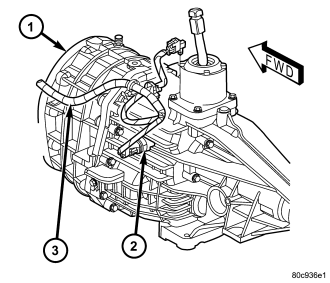
Vehicles equipped with a manual transmission (1) have a normally open, spring-loaded plunger type backup lamp switch (2). Vehicles with an optional electronic automatic transmission have a Transmission Range Sensor (TRS) that is used to perform several functions, including that of the backup lamp switch. The TRS is described in further detail elsewhere in this service information. Refer to the service and diagnostic information for the automatic transmission type installed in the vehicle.
The backup lamp switch is located in a threaded hole on the side of the manual transmission housing. The switch has a threaded body and a hex formation near the plunger end of the switch. An integral connector receptacle at the end of the switch opposite the plunger connects the switch to the vehicle electrical system through a take out and connector of the engine wire harness. When installed, only the switch connector and the hex formation are visible on the outside of the transmission housing.
The backup lamp switch cannot be adjusted or repaired and, if ineffective or damaged, the entire switch unit must be replaced.
OPERATION
The backup lamp switch controls a path to ground for the Totally Integrated Power Module (TIPM) on the reverse switch signal circuit. The TIPM reads this input through an internal pull-up, then controls an output through a high side driver that regulates the flow of battery voltage to the backup lamp bulbs as appropriate on the backup lamp feed circuit. The switch plunger is mechanically actuated by the gearshift mechanism within the transmission, which will depress the switch plunger and close the switch contacts whenever the REVERSE gear has been selected. The switch receives ground at all times through a take out and eyelet terminal of the engine wire harness that is secured by a nut to a ground stud on the body sheet metal within the engine compartment of the vehicle.
The backup lamp switch as well as the hard wired inputs and outputs of the switch may be diagnosed using conventional diagnostic tools and procedures. Refer to the appropriate wiring information.