VALVE-A/C EXPANSION
DESCRIPTION
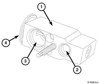
The A/C expansion valve controls the amount of refrigerant entering the A/C evaporator. The A/C expansion valve is of a thermostatic expansion valve (TXV) design and consists of an aluminum H-valve type body (1) with an inlet port (2), outlet port (3) and an integral thermal sensor (4).
The A/C expansion valve is located between the A/C refrigerant lines and the A/C evaporator in the engine compartment.
OPERATION
The A/C expansion valve controls the high-pressure, low temperature liquid refrigerant from the liquid line and converts it into a low-pressure, low-temperature mixture of liquid and gas before it enters the A/C evaporator. A mechanical sensor in the A/C expansion valve monitors the temperature and pressure of the refrigerant leaving the A/C evaporator through the suction line, and adjusts the orifice size at the liquid line port to let the proper amount of refrigerant into the A/C evaporator to meet the vehicle A/C cooling requirements. Controlling the refrigerant flow through the A/C evaporator ensures that none of the refrigerant leaving the A/C evaporator is still in a liquid state, which could damage the A/C compressor.
NOTE: Replacement of the refrigerant line O-ring seals and gaskets is required anytime a refrigerant line is opened. Failure to replace the rubber O-ring seals and metal gaskets could result in a refrigerant system leak.
The A/C expansion valve is factory calibrated and cannot be adjusted or repaired and must be replaced if found inoperative or damaged.
REMOVAL
WARNING: Refer to the applicable warnings and cautions for this system before performing the following operation (refer to 24 - HEATING & AIR CONDITIONING/PLUMBING - WARNING) and (refer to 24 - HEATING & AIR CONDITIONING/PLUMBING - CAUTION). Failure to follow the warnings and cautions could result in possible personal injury or death.
1. Disconnect and isolate the negative battery cable.
2. Recover the refrigerant from the refrigerant system (refer to 24 - HEATING & AIR CONDITIONING/PLUMBING - STANDARD PROCEDURE - REFRIGERANT SYSTEM RECOVERY).
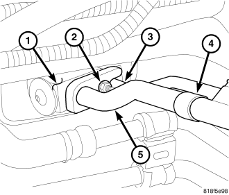
3. Remove the nut (2) that secures the A/C liquid line (3) and A/C suction line (5) to the A/C expansion valve (1).
4. Disconnect the A/C liquid and suction lines from the A/C expansion valve, remove and discard the O-ring seals and position the refrigerant lines out of the way.
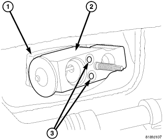
5. Remove the two bolts (3) that secure the A/C expansion valve (2) to the evaporator tube tapping block (1).
6. Remove the A/C expansion valve from the evaporator tube tapping block and remove and discard the O-ring seals.
7. Install plugs in, or tape over the opened refrigerant line and evaporator tube fittings and all expansion valve ports.
INSTALLATION
CAUTION: Be certain to adjust the refrigerant oil level when servicing the A/C refrigerant system (refer to 24 - HEATING & AIR CONDITIONING/PLUMBING/REFRIGERANT OIL - STANDARD PROCEDURE - REFRIGERANT OIL LEVEL). Failure to properly adjust the refrigerant oil level will prevent the A/C system from operating as designed and can cause serious A/C compressor damage.
NOTE: When replacing multiple A/C system components, refer to the Refrigerant Oil Capacities chart to determine how much oil should be added to the refrigerant system (refer to 24 - HEATING & AIR CONDITIONING/PLUMBING/REFRIGERANT OIL - STANDARD PROCEDURE - REFRIGERANT OIL LEVEL).
NOTE: Replacement of the refrigerant line O-ring seals and gaskets is required anytime a refrigerant line is opened. Failure to replace the rubber O-ring seals and metal gaskets could result in a refrigerant system leak.
1. Remove the tape or plugs from the opened refrigerant lines and evaporator tube fittings and all of the expansion valve ports.
2. Lubricate new O-ring seals with clean refrigerant oil and install them onto the refrigerant line and evaporator tube fittings. Use only the specified O-rings as they are made of a special material for the R-134a system. Use only refrigerant oil of the type recommended for the A/C compressor in the vehicle.
3. Install the A/C expansion valve (2) onto the evaporator tube tapping block (1).
4. Install the two bolts (3) that secure the A/C expansion valve to the evaporator tube tapping block. Tighten the bolts to 11 N·m (97 in. lbs.).
5. Connect the A/C liquid line (3) and A/C suction line (5) to the A/C expansion valve (1) and install the retaining nut (2). Tighten the nut to 8 N·m (70 in. lbs.).
6. Reconnect the negative battery cable.
7. Evacuate the refrigerant system (refer to 24 - HEATING & AIR CONDITIONING/PLUMBING - STANDARD PROCEDURE - REFRIGERANT SYSTEM EVACUATE).
8. Adjust the refrigerant oil level (refer to 24 - HEATING & AIR CONDITIONING/PLUMBING/REFRIGERANT OIL - STANDARD PROCEDURE - REFRIGERANT OIL LEVEL).
9. Charge the refrigerant system (refer to 24 - HEATING & AIR CONDITIONING/PLUMBING - STANDARD PROCEDURE - REFRIGERANT SYSTEM CHARGE).