MODULE-TOTALLY INTEGRATED POWER
DESCRIPTION
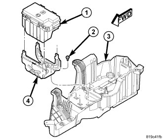
All of the electrical current distributed throughout this vehicle is directed through the standard equipment Totally Integrated Power Module (TIPM) (1). The molded plastic TIPM housing is located in the right front corner of the engine compartment, just behind the air cleaner housing and in front of the battery. The TIPM housing has a molded plastic cover. The TIPM cover is easily removed for service access and has a convenient fuse layout label affixed to the inside surface of the cover to ensure proper component identification.
The TIPM housing is secured to the TIPM mounting bracket (4) by four clips integral to the TIPM housing. The TIPM mounting bracket is secured to the battery tray (3) with four screws (2). All of the TIPM outputs are through the integral engine compartment wire harness.
OPERATION
All of the current to the Totally Integrated Power Module (TIPM) comes directly from the positive battery cable to a stud located on the top of the TIPM. The cable is secured to the TIPM stud with a nut. Internal connection of all the TIPM circuits is accomplished by an intricate network of hard wiring and bus bars. Refer to Wiring Diagrams for complete circuit diagrams.
The fuses, relays and TIPM housing assembly are available for service replacement.
REMOVAL
NOTE: Left hand drive gasoline engine shown, left hand drive diesel similar. Right hand drive gasoline and diesel similar with the battery and related components packaged on the left side of the engine compartment.
1. Open hood.
2. Disconnect and isolate the battery negative cable.
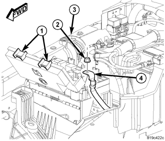
3. Release the Totally Integrated Power Module (TIPM) cover retaining clips (1) and open the TIPM cover.
4. Remove the TIPM positive cable retaining nut (2) and remove the cable (4) from the stud.
5. Depress the four mounting clips to disengage and remove the TIPM housing (1) from its mounting bracket (4).
6. Disconnect each of the seven TIPM wire harness connectors.
7. Remove the TIPM from the vehicle.
INSTALLATION
CAUTION: The original Cab Compartment Node (CCN) and Powertrain Control Module (PCM) must be installed and functioning properly prior to powering up the new Totally Integrated Power Module (TIPM). The TIPM receives vehicle configuration data from the CCN and Vehicle Identification Number information from the PCM. If configuration information becomes lost or corrupted, the data can be obtained from DealerCONNECT
NOTE: Left hand drive gasoline engine shown, left hand drive diesel similar. Right hand drive gasoline and diesel similar with the battery and related components packaged on the left side of the engine compartment.
1. Position the TIPM (1) into the engine compartment.
2. Connect each of the seven TIPM wire harness connectors.
3. Position the TIPM (1) onto the mounting bracket (4) and push down until the mounting clips are fully seated.
4. Position the TIPM positive cable (4) onto the mounting stud and install the retaining nut (2). Tighten the nut to 9 - 11 N·m (80 - 100 in. lbs.).
5. Open the TIPM cover (1) and fully seat the Airbag fuse holder (two fuses in one yellow carrier) and the Ignition Off Draw (IOD) fuse.
6. Connect the battery negative cable.
7. Close the hood.
8. Insert the ignition key and turn it to the “RUN” position and wait twelve seconds. The TIPM will collect the necessary vehicle configuration and VIN data from the CCN and PCM at this time. After twelve seconds turn the ignition key to the “OFF” position and then back to the “ON” position and verify proper vehicle systems operation.