DIFFERENTIAL-TRAC-LOK
OPERATION-TRAC-LOK®
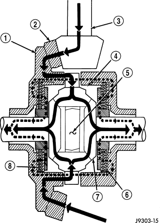
This differential clutches are engaged by two concurrent forces. The first being the preload force exerted through Belleville spring washers within the clutch packs (6) (8). The second is the separating forces generated by the side gears (7) as torque is applied through the ring gear (2).
This design provides the differential action needed for turning corners and for driving straight ahead during periods of unequal traction. When one wheel looses traction, the clutch packs transfer additional torque to the wheel having the most traction. This differential resist wheel spin on bumpy roads and provide more pulling power when one wheel looses traction. Pulling power is provided continuously until both wheels loose traction. If both wheels slip due to unequal traction, Trac-lok® operation is normal. In extreme cases of differences of traction, the wheel with the least traction may spin.
DISASSEMBLY
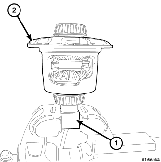
1. Remove ring gear.
2. Clamp side gear Fixture 6963A (1) in a vise and set differential case (2) on the fixture.
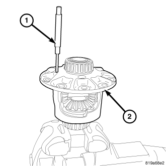
3. Remove pinion gear mate shaft roll pin from differential case (1) with a hammer and punch (2).
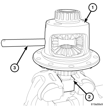
4. Rotate differential case (1) on the fixture (2) and remove pinion mate shaft (3).
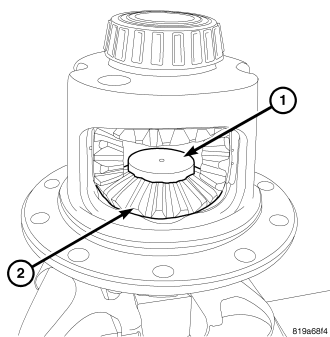
5. Lubricate and install disc (1) without threaded hole from Trac-lok® Tool C-4487 into lower side gear (2).
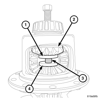
6. Lubricate and install disc (1) with threaded hole from Trac-lok® Tool C-4487 into upper side gear (2). Thread forcing screw (3) from Trac-lok® Tool C-4487 into upper disc until it contacts the lower disc (4).
NOTE: Slot in threaded upper disc (1) can be used to prevent it from turning using a screw driver.
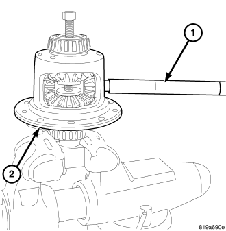
7. Tighten forcing screw to compress belleville springs in clutch packs. Then Insert turning bar (1) from Trac-lok® Tool C-4487 into the pinion mate shaft hole in the case (2).
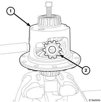
8. Rotate differential case (1) with turning bar until the pinion gears (1) and washers can be removed.
NOTE: Loosen forcing screw in small increments to relieve clutch pack tension if differential case can not be rotated.
9. Remove Forcing Screw, Step Plate and Threaded Adapter.
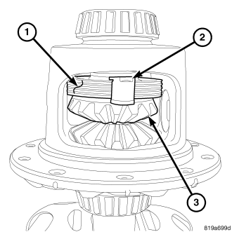
10. Remove upper clutch pack (1), clutch pack retainers (2) and upper side gear (3) from case.
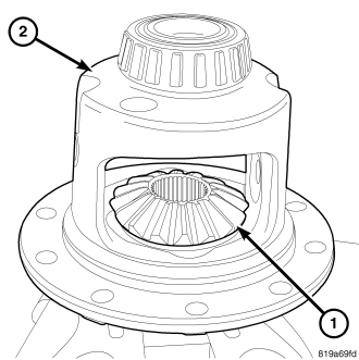
11. Remove lower clutch pack, clutch pack retainers and lower side gear (1) from case (2).
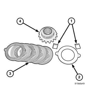
12. Remove clutch pack retainers (1), clutch pack (3) belleville spring (2) from side gear (4). Keep plates in order during removal.
ASSEMBLY
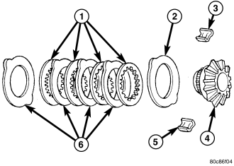
NOTE: New Plates and discs with fiber coating (no grooves or lines) must be presoaked in Friction Modifier before assembly. Soak plates and discs for a minimum of 20 minutes.
1. Lubricate components with gear lubricant.
2. Assemble clutch discs (1), plates (6) and belleville spring (2) into packs and secure disc packs with retainers (5).
NOTE: Belleville spring (2) is position with the convex side against the side gear.
3. Position assembled clutch disc packs on the side gear (4) hubs.
4. Install lower clutch pack and side gear (1) in the differential case (2), with retaining clips seated in the case pocket.
5. Install upper clutch disc pack (1) retaining clips (2) and side gear (3) with seated in the case pocket.
6. Lubricated and install discs into side gears from Trac-lok® Tool C-4487. Install forcing screw from Trac-lok® Tool C-4487 and thread screw to compress belleville springs in clutch packs.
7. Install pinion gears (2) in side gears opposite each other.
8. Rotate differential case (2) with turning bar (1) from Trac-lok® Tool C-4487 until pinion gears align with mate shaft holes in the case.
NOTE: Loosen forcing screw in small increments to relieve clutch pack tension if differential case can not be rotated.
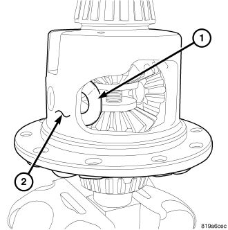
9. Install pinion gear thrust washers (1) between the gear and case (2). Align washers with mate shaft hole in the case.
10. Remove forcing screw upper disc from side gear.
11. Remove lower disc (1) from side gear (2).
12. Install pinion mate shaft (3) in case (1).
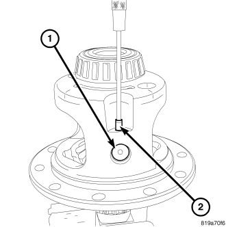
13. Install pinion mate shaft (1) roll pin (2).
14. Install ring gear.
15. Lubricate all differential components with gear lubricant.