DIFFERENTIAL-TRU-LOK
DESCRIPTION
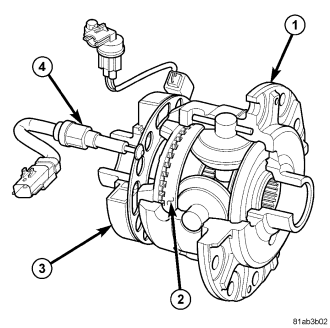
Tru-Lok is an electronically locking differential (1). The differential has four pinion gears, three pinion shafts and two side gears. On the back side of one side gear (2) is half of the dog clutch.
NOTE: The electric locking differential is serviced as an assembly.
A 12 volt electromagnetic coil (3) on the differential is controlled by the Totally Integrated Power Module (TIPM). When the coil (3) is energized the dog clutch is engaged which locks the one side gear to the differential case. This action locks the axles and triggers a switch (4) in the differential housing which activates the Tru-Lok indicator light on the dash.
OPERATION
Pressing a two-way momentary rocker switch on the switch bank request axle lock. The first press DOWN requests rear axle to be locked, every other press DOWN toggles between "front and rear axle lock" and "rear axle lock" request states. Press rocker switch UP requests both axles to be unlocked. The switch is on the IP in the switch bank. The switch bank sends a message to the Cabin Cluster Node (CCN). The CCN handles the switch debounce and switch diagnostics. Any one message sent by the CCN on the network is a valid switch change. The CCN passes the information to the Totally Integrated Power Module (TIPM) via a CAN B message. The TIPM will process the switch info received from CAN B, control the outputs as required by the Axle Lock Electrical Requirements, and send a lighting request to the CCN via CAN B. There are three telltales on the cluster, "Rear”, "Front”, and "Lock". The telltales will be off if the axles are unlocked, flashing if there is a pending request to lock but the axles are not yet locked (transition to lock, torque-locked, or conditions not correct), and flashing rapidly if there is a fault. The “Front” and “Rear” telltales will match the front and rear differential states. The “Lock” telltale will be on solid if either the “Front” or “Rear” telltale is on or blinking. The TIPM will send the axle lock status message to the ESP module via CAN C.
AXLE LOCK ELECTRICAL REQUIREMENTS
DIFFERENTIAL LOCK
- Vehicle speed of 16 KPH (10 MPH) or below
- Transfer case in 4 LO position
- Switch request message for the corresponding axle/s has been received
- Ignition switch in the RUN or START position
- No system, module. or switch faults have been detected
DIFFERENTIAL UNLOCK
- Transfer case in 4 HI, 2 WD, or Neutral
- Loss of ignition switch signal, vehicle speed signal, transfer case signal
- Vehicle speed of 50 KPH (30 MPH) or higher
- Valid switch message received
AXLE FAIL-SAFE
- Axles will UNLOCK with ignition switch in either the OFF or ACC position.
- Axles will not LOCK if there is no ignition switch, vehicle speed, or transfer case position signal. Axles will UNLOCK with the loss of any of these signals.
- Axles will not LOCK if the ignition switch is OFF.
- Axles will UNLOCK if a switch failure is detected.
Software Latch Feature: The Totally Integrated Power Module (TIPM) will have a software latch of the axle switch during an ignition switch OFF when the vehicle is in 4 LO transfer case position. Upon ignition key RUN or START the TIPM shall check to verify conditions are correct for an axle lock and automatically lock the axles that were locked before the ignition was turned OFF.
NOTE: The electric locking differential is serviced as an assembly.
REMOVAL
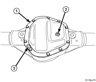
1. Remove differential fill plug (2).
2. Remove differential cover (1) and drain fluid.
3. Remove axle shafts.
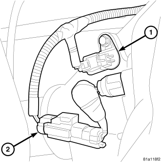
4. Remove Tru-Lok harness from the coil (1) and indicator switch (2).
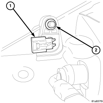
5. Remove Tru-Lok coil connector (1) bolt (2).
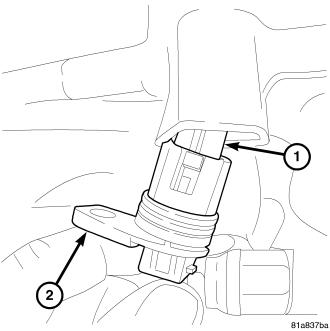
6. Remove Tru-Lok coil connector from the axle housing and remove coil harness (1) from the connector (2).
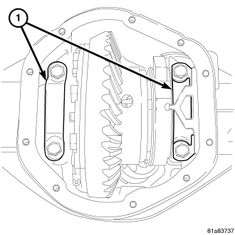
7. Loosen differential bearing cap (1) bolts.
8. Position Spreader W-129-B with Adapter Kit 6987B on differential locating holes. Install hold-down clamps and tighten the turnbuckle finger-tight.
9. Install a Pin C-3288-B at the left side of the differential housing. Attach Dial Indicator C-3339A to pin. Load indicator plunger against the opposite side of the housing and zero the indicator.
10. Spread housing while measuring the distance with the dial indicator.
CAUTION: Never spread housing over 0.50 mm (0.020 in). Failure to follow these instructions will damage the housing.
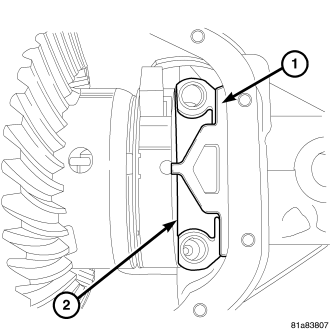
11. Remove dial indicator.
12. Holding differential case in position, remove differential bearing cap bolts.
13. Remove coil anti-rotation bracket (1) from the bearing cap (2), then remove both bearing caps.
14. Remove differential case from housing and tag differential bearing cups and shims location.
15. Remove spreader from housing.
16. Clean the housing cavity with flushing oil, light engine oil or lint free cloth.
NOTE: Do not use water, steam, kerosene or gasoline for cleaning.
INSTALLATION
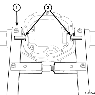
NOTE: If replacement differential bearings or differential case are being installed, differential side bearing shim requirements may change. Refer Adjustments (Differential Bearing Preload and Gear Backlash) to determine the proper shim selection.
1. Position Spreader W-129-B (1) and with dowel pins from Adapter Kit 6987B seated in housing locating holes. Install hold-down clamps (2) and tighten turnbuckle finger-tight.
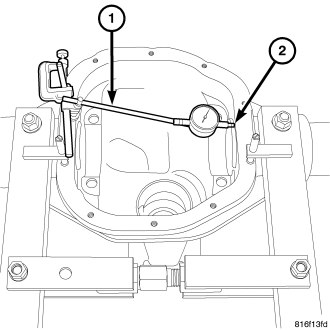
2. Install Pin C-3288-B at the left side of the differential housing. Attach Dial Indicator C-3339A (1) to pin. Load the indicator plunger (2) against the opposite side of the housing and zero the indicator.
3. Spread the housing while measuring the distance with the dial indicator.
CAUTION: Never spread housing over 0.50 mm (0.020 in). Failure to follow these instructions will damage the housing.
4. Remove the dial indicator.
5. Install differential case into the housing with differential bearing cups and shims in their original locations.
6. Install bearing caps (2) in their original locations and coil anti-rotation bracket (1).
7. Loosely install differential bearing cap bolts.
8. Remove spreader.
9. Tighten bearing cap (1) bolts in a criss-cross pattern to 108 N·m (80 ft. lbs.).
10. Install Tru-Lok coil connector (2) to the coil harness (1).
11. Install Tru-Lok coil connector (1) bolt (2).
12. Install Tru-Lok harness to the coil (1) and indicator switch (2).
13. Install axle shafts.
14. Install differential cover (1).