OCCUPANT RESTRAINT CONTROLLER
DESCRIPTION
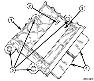
The Occupant Restraint Controller (ORC) (1) is secured with four nuts to four studs on a stamped steel mounting bracket welded onto the top of the floor panel transmission tunnel between the two front seats beneath the floor console and rearward of the transmission gearshift mechanism in the passenger compartment of the vehicle. Concealed within a hollow in the center of the molded plastic ORC housing is the electronic circuitry of the ORC which includes a microprocessor, an electronic impact sensor, an electronic safing sensor, and an energy storage capacitor. A molded plastic end cover plate with a rubber O-ring seal is secured to the open end of the ORC housing with two integral latch features to enclose and protect the internal electronic circuitry and components.
An arrow (2) printed on the label (3) on the top of the ORC housing provides a visual verification of the proper orientation of the unit, and should always be pointed toward the front of the vehicle. The ORC housing has four integral mounting flanges (5) with metal sleeves to provide crush protection. Two molded plastic electrical connector receptacles (4) are integral to the end cover plate. These receptacles connect the ORC to the vehicle electrical system through dedicated take outs and connectors from the instrument panel and the body wire harnesses.
The impact sensor and safing sensor internal to the ORC are calibrated for the specific vehicle, and are only serviced as a unit with the ORC. In addition, there are unique versions of the ORC for vehicles with or without optional seat-mounted side airbags. The ORC cannot be repaired or adjusted and, if damaged or ineffective, it must be replaced.
OPERATION
The microprocessor in the Occupant Restraint Controller (ORC) contains the supplemental restraint system logic circuits and controls all of the supplemental restraint system components. The ORC uses On-Board Diagnostics (OBD) and can communicate with other electronic modules in the vehicle as well as with the diagnostic scan tool using the Controller Area Network (CAN) data bus. This method of communication is used for control of the airbag indicator in the ElectroMechanical Instrument Cluster (EMIC) (also known as the Cab Compartment Node/CCN) and for supplemental restraint system diagnosis and testing through the 16-way data link connector located on the driver side lower edge of the instrument panel. (Refer to 8 - ELECTRICAL/INSTRUMENT CLUSTER/AIRBAG INDICATOR - OPERATION).
The ORC microprocessor continuously monitors all of the supplemental restraint system electrical circuits to determine the system readiness. If the ORC detects a monitored system fault, it sets an active and stored Diagnostic Trouble Code (DTC) and sends electronic messages to the EMIC over the CAN data bus to turn ON the airbag indicator. An active fault only remains for the duration of the fault, or in some cases for the duration of the current ignition switch cycle, while a stored fault causes a DTC to be stored in memory by the ORC. For some DTCs, if a fault does not recur for a number of ignition cycles, the ORC will automatically erase the stored DTC. For other internal faults, the stored DTC is latched forever.
On vehicles so equipped, the ORC provides voltage to the seat track position sensors on the inboard passenger and driver side front seat upper seat tracks. The ORC then monitors return inputs from each of the sensors on dedicated hard wired data communication circuits. The seat track position sensors provide additional logic inputs to the ORC microprocessor that allow it to determine the position of the front seat passenger and the driver relative to the front airbags for determining the force level with which to deploy the multistage front airbags.
On vehicles equipped with the Occupant Classification System (OCS), the ORC communicates with the Occupant Classification Module (OCM) over the CAN data bus. The ORC will internally disable the passenger airbag and seat belt tensioner deployment circuits if the OCM detects that the passenger side front seat is unoccupied or that it is occupied by a load that is inappropriate for an airbag deployment. The ORC also provides a control output to the passenger airbag on/off indicator through the passenger airbag indicator driver circuit. The OCM notifies the ORC when it has detected a monitored system fault and stored a DTC in its memory for any ineffective OCS component or circuit, then the ORC sets a DTC and controls the airbag indicator operation accordingly.
The ORC receives battery current through two circuits; a fused ignition switch output (run) circuit through a fuse in the Totally Integrated Power Module (TIPM), and a fused ignition switch output (run-start) circuit through a second fuse in the TIPM. The ORC receives ground through a ground circuit and take out of the instrument panel wire harness. These connections allow the ORC to be operational whenever the ignition switch is in the START or ON positions. Refer to the appropriate wiring information for additional details.
The ORC also contains an energy-storage capacitor. When the ignition switch is in the START or ON positions, this capacitor is continually being charged with enough electrical energy to deploy the supplemental restraint components for up to one second following a battery disconnect or failure. The purpose of the capacitor is to provide backup supplemental restraint system protection in case there is a loss of battery current supply to the ORC during an impact.
Two sensors are contained within the ORC, an electronic impact sensor and a safing sensor. The ORC also monitors inputs from two remote front impact sensors located on the back of the right and left ends of the front end module carrier inboard of the headlamps near the front of the vehicle. The electronic impact sensors are accelerometers that sense the rate of vehicle deceleration, which provides verification of the direction and severity of an impact. On vehicles equipped with optional seat-mounted side airbags the ORC also monitors inputs from an internal rollover sensor and two additional remote impact sensors located on the left and right inner B-pillars to control deployment of the seat airbag units.
The safing sensor is an electronic accelerometer sensor within the ORC that provides an additional logic input to the ORC microprocessor. The safing sensor is used to verify the need for a supplemental restraint deployment by detecting impact energy of a lesser magnitude than that of the primary electronic impact sensors, and must exceed a safing threshold in order for the airbags to deploy. Vehicles equipped with optional seat-mounted side airbags feature a second safing sensor within the ORC to provide confirmation to the ORC microprocessor of side impact forces. This second safing sensor is a bi-directional unit that detects impact forces from either side of the vehicle.
Pre-programmed decision algorithms in the ORC microprocessor determine when the deceleration rate as signaled by the impact sensors and the safing sensors indicate an impact that is severe enough to require supplemental restraint system protection and, based upon the severity of the monitored impact, determines the level of front airbag deployment force required for each front seating position. When the programmed conditions are met, the ORC sends the proper electrical signals to deploy the dual multistage front airbags at the programmed force levels, the front seat belt tensioners and, if the vehicle is so equipped, either side airbag unit. For vehicles equipped with the OCS, the passenger front airbag and seat belt tensioner will be deployed by the ORC only if enabled by the OCM messages (passenger airbag on/off indicator OFF) at the time of the impact.
The hard wired inputs and outputs for the ORC may be diagnosed using conventional diagnostic tools and procedures. Refer to the appropriate wiring information. However, conventional diagnostic methods will not prove conclusive in the diagnosis of the ORC or the electronic controls or communication between other modules and devices that provide features of the supplemental restraint system. The most reliable, efficient, and accurate means to diagnose the ORC or the electronic controls and communication related to ORC operation requires the use of a diagnostic scan tool. Refer to the appropriate diagnostic information.
REMOVAL
WARNING: To avoid serious or fatal injury on vehicles equipped with optional seat-mounted side airbags, disable the supplemental restraint system before attempting any occupant restraint controller diagnosis or service. The occupant restraint controller contains a rollover sensor, which enables the system to deploy the side airbags in the event of a vehicle rollover event. If an occupant restraint controller is accidentally rolled during service while still connected to battery power, the side airbags will deploy. Disconnect and isolate the battery negative (ground) cable, then wait two minutes for the system capacitor to discharge before performing further diagnosis or service. This is the only sure way to disable the supplemental restraint system. Failure to take the proper precautions could result in accidental airbag deployment.
WARNING: To avoid serious or fatal injury on vehicles equipped with airbags, disable the supplemental restraint system before attempting any steering wheel, steering column, airbag, occupant classification system, seat belt tensioner, impact sensor, or instrument panel component diagnosis or service. Disconnect and isolate the battery negative (ground) cable, then wait two minutes for the system capacitor to discharge before performing further diagnosis or service. This is the only sure way to disable the supplemental restraint system. Failure to take the proper precautions could result in accidental airbag deployment.
WARNING: To avoid serious or fatal injury, never strike or drop the occupant restraint controller, as it can damage the impact sensor or affect its calibration. The occupant restraint controller contains the impact sensor, which enables the system to deploy the supplemental restraints. If an occupant restraint controller is accidentally dropped during service, the module must be scrapped and replaced with a new unit. Failure to observe this warning could result in accidental, incomplete, or improper supplemental restraint deployment.
CAUTION: On vehicles equipped with the Occupant Classification System (OCS), never replace both the Occupant Restraint Controller (ORC) and the Occupant Classification Module (OCM) at the same time. If both require replacement, replace one. Then perform the supplemental restraint verification test before replacing the other. Both the ORC and the OCM store OCS calibration data, which they transfer to one another when one of them is replaced. If both are replaced at the same time, an irreversible fault will be set in both modules.
NOTE: Several different Occupant Restraint Controllers (ORC) are available for this vehicle. For vehicles equipped with the optional seat-mounted side airbags the ORC contains a second bi-directional safing sensor.
1. Disconnect and isolate the battery negative cable. Wait two minutes for the system capacitor to discharge before further service.
2. Remove the center console from the top of the floor panel transmission tunnel. (Refer to 23 - BODY/INTERIOR/CENTER CONSOLE - REMOVAL).
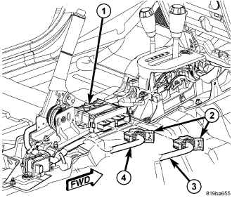
3. Unlatch and disconnect the instrument panel wire harness (4) and body wire harness (3) connectors (2) from the Occupant Restraint Controller (ORC) (1) connector receptacles located on the right side of the module. To disconnect the wire harness connectors from the ORC, depress the release tab and lift the lever arm on each connector.
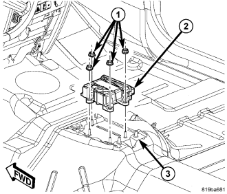
4. Remove the four nuts (1) that secure the ORC (2) to the three studs on the ORC mount (3) welded onto the top of the floor panel transmission tunnel.
5. Remove the ORC from the ORC mount.
INSTALLATION
WARNING: To avoid serious or fatal injury on vehicles equipped with optional seat-mounted side airbags, disable the supplemental restraint system before attempting any occupant restraint controller diagnosis or service. The occupant restraint controller contains a rollover sensor, which enables the system to deploy the side airbags in the event of a vehicle rollover event. If an occupant restraint controller is accidentally rolled during service while still connected to battery power, the side airbags will deploy. Disconnect and isolate the battery negative (ground) cable, then wait two minutes for the system capacitor to discharge before performing further diagnosis or service. This is the only sure way to disable the supplemental restraint system. Failure to take the proper precautions could result in accidental airbag deployment.
WARNING: To avoid serious or fatal injury on vehicles equipped with airbags, disable the supplemental restraint system before attempting any steering wheel, steering column, airbag, occupant classification system, seat belt tensioner, impact sensor, or instrument panel component diagnosis or service. Disconnect and isolate the battery negative (ground) cable, then wait two minutes for the system capacitor to discharge before performing further diagnosis or service. This is the only sure way to disable the supplemental restraint system. Failure to take the proper precautions could result in accidental airbag deployment.
WARNING: To avoid serious or fatal injury, never strike or drop the occupant restraint controller, as it can damage the impact sensor or affect its calibration. The occupant restraint controller contains the impact sensor, which enables the system to deploy the supplemental restraints. If an occupant restraint controller is accidentally dropped during service, the module must be scrapped and replaced with a new unit. Failure to observe this warning could result in accidental, incomplete, or improper supplemental restraint deployment.
CAUTION: On vehicles equipped with the Occupant Classification System (OCS), never replace both the Occupant Restraint Controller (ORC) and the Occupant Classification Module (OCM) at the same time. If both require replacement, replace one. Then perform the supplemental restraint verification test before replacing the other. Both the ORC and the OCM store OCS calibration data, which they transfer to one another when one of them is replaced. If both are replaced at the same time, an irreversible fault will be set in both modules.
NOTE: Several different Occupant Restraint Controllers (ORC) are available for this vehicle. For vehicles equipped with the optional seat-mounted side airbags the ORC contains a second bi-directional safing sensor.
1. Carefully position the Occupant Restraint Controller (ORC) (2) onto the four studs of the ORC mount (3) on the floor panel transmission tunnel. When the ORC is correctly positioned, the bottom of the housing will fit flush with the mount and the orientation arrow on the label on top of the housing will be pointed forward in the vehicle.
2. Install and tighten the four nuts (1) that secure the ORC to the studs of the ORC mount. Tighten the nuts to 9 N·m (80 in. lbs.).
3. Reconnect the body wire harness (3) and instrument panel wire harness (4) connectors (2) to the ORC connector receptacles located on the right side of the module (1). Be certain that the latches on the connectors are each fully engaged.
4. Reinstall the center console onto the top of the floor panel transmission tunnel. (Refer to 23 - BODY/INTERIOR/CENTER CONSOLE - INSTALLATION).
5. Do not reconnect the battery negative cable at this time. The supplemental restraint system verification test procedure should be performed following service of any supplemental restraint system component. (Refer to 8 - ELECTRICAL/RESTRAINTS - STANDARD PROCEDURE - VERIFICATION TEST).