SEAT - FRONT
DESCRIPTION
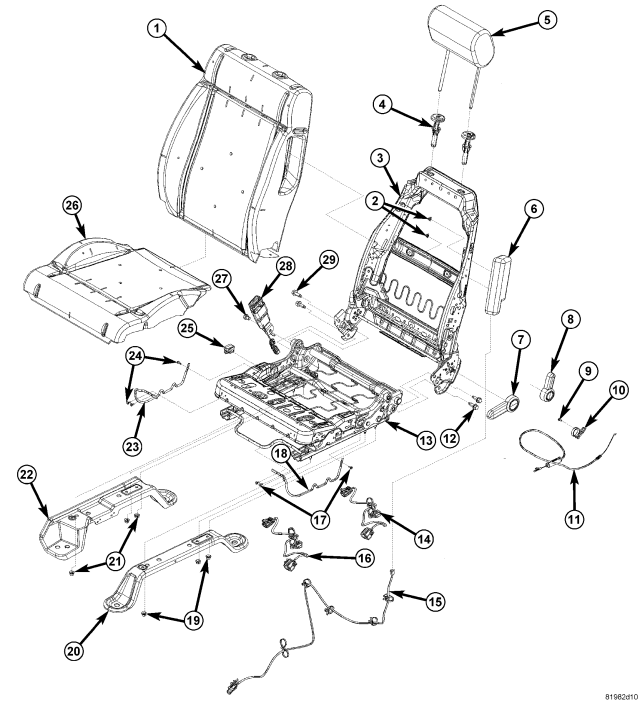
| LEFT HAND SEAT – 2 WAY ADJUSTER |
| 1 - SEAT BACK CUSHION/COVER |
| 2 - AIR BAG NUTS 7 N·m (5 ft. lbs.) |
| 3 - SEAT BACK FRAME |
| 4 - HEADREST SLEEVES |
| 5 - HEADREST |
| 6 - SEAT AIR BAG |
| 7 - RECLINER HANDLE |
| 8 - EASY ENTRY HANDLE |
| 9 - SCREW |
| 10 - EASY ENTRY CABLE ROUTER |
| 11 - EASY ENTRY CABLE |
| 12 - BACK ASSEMBLY BOLTS 47 N·m (34.5 ft. lbs.) |
| 13 - SEAT CUSHION FRAME |
| 14 - WIRE HARNESS |
| 15 - SEAT AIR BAG HARNESS |
| 16 - WIRE HARNESS |
| 17 - RIVETS |
| 18 - TRIM ATTACHMENT WIRE |
| 19 - RISER NUTS 28 N·m (20.5 ft. lbs.) |
| 20 - OUTBOARD RISER |
| 21 - RISER NUTS 28 N·m (20.5 ft. lbs.) |
| 22 - INBOARD RISER |
| 23 - TRIM ATTACHMENT WIRE |
| 24 - RIVETS |
| 25 - SEAT TRACK POSITION SENSOR |
| 26 - SEAT CUSHION/COVER |
| 27 - SEAT BELT BUCKLE BOLT 50 N·m (37 ft. lbs.) |
| 28 - SEAT BELT BUCKLE |
| 29 - BACK ASSEMBLY BOLTS 47 N·m (34.5 ft. lbs.) |
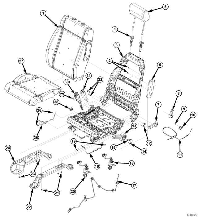
| LEFT HAND SEAT – 4 WAY ADJUSTER |
| 1 - SEAT BACK CUSHION/COVER |
| 2 - AIR BAG NUTS 7 N·m (5 ft. lbs.) |
| 3 - SEAT BACK FRAME |
| 4 - HEADREST SLEEVES |
| 5 - HEADREST |
| 6 - SEAT AIR BAG |
| 7 - RECLINER HANDLE |
| 8 - EASY ENTRY HANDLE |
| 9 - SCREW |
| 10 - EASY ENTRY CABLE ROUTER |
| 11 - EASY ENTRY CABLE |
| 12 - BACK ASSEMBLY BOLTS 47 N·m (34.5 ft. lbs.) |
| 13 - LIFT HANDLE |
| 14 - LIFT HANDLE CAP |
| 15 - LIFT HANDLE SCREW |
| 16 - WIRE HARNESS |
| 17 - SEAT AIR BAG HARNESS |
| 18 - RIVETS |
| 19 - TRIM ATTACHMENT WIRE |
| 20 - WIRE HARNESS |
| 21 - RISER NUTS 28 N·m (20.5 ft. lbs.) |
| 22 - OUTBOARD RISER |
| 23 - RISER NUTS 28 N·m (20.5 ft. lbs.) |
| 24 - INBOARD RISER |
| 25 - TRIM ATTACHMENT WIRE |
| 26 - RIVETS |
| 27 - SEAT CUSHION/COVER |
| 28 - SEAT TRACK POSITION SENSOR |
| 29 - SEAT BELT BUCKLE BOLT 50 N·m (37 ft. lbs.) |
| 30 - SEAT BELT BUCKLE |
| 31 - SEAT BELT BUCKLE |
| 32 - BACK ASSEMBLY BOLTS 47 N·m (34.5 ft. lbs.) |
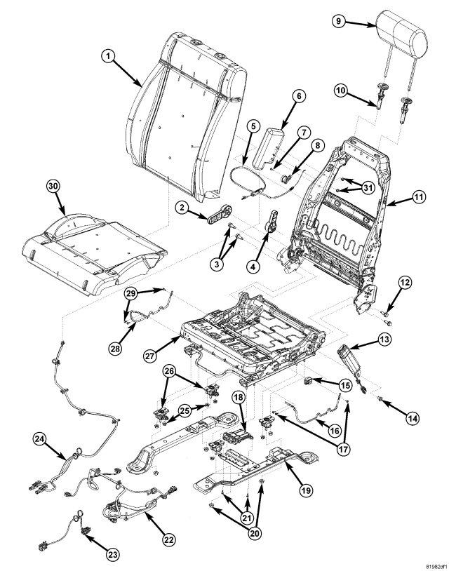
| RIGHT HAND SEAT – 2 WAY ADJUSTER |
| 1 - SEAT BACK CUSHION/COVER |
| 2 - RECLINER HANDLE |
| 3 - BACK ASSEMBLY BOLTS 47 N·m (34.5 ft. lbs.) |
| 4 - EASY ENTRY HANDLE |
| 5 - EASY ENTRY CABLE |
| 6 - SEAT AIR BAG |
| 7 - SCREW |
| 8 - EASY ENTRY CABLE ROUTER |
| 9 - HEADREST |
| 10 - HEADREST SLEEVE |
| 11 - SEAT BACK FRAME |
| 12 - BACK ASSEMBLY BOLTS 47 N·m (34.5 ft. lbs.) |
| 13 - SEAT BELT BUCKLE |
| 14 - SEAT BELT BUCKLE BOLT 50 N·m (37 ft. lbs.) |
| 15 - SEAT TRACK POSITION SENSOR |
| 16 - TRIM ATTACHMENT WIRE |
| 17 - RIVETS |
| 18 - OCS MODULE |
| 19 - INBOARD RISER |
| 20 - CENTER OCS STRAIN GAUGE STUD NUT 45 N·m (33 ft. lbs.) |
| 21 - MODULE SCREWS |
| 22 - WIRE HARNESS |
| 23 - WIRE HARNESS |
| 24 - AIR BAG HARNESS |
| 25 - OCS RISER NUTS 28 N·m (21 ft. lbs.) |
| 26 - OCS STRAIN GAUGE (4) |
| 27 - SEAT CUSHION FRAME |
| 28 - TRIM ATTACHMENT WIRE |
| 29 - RIVETS |
| 30 - SEAT CUSHION/COVER |
| 31 - AIR BAG NUTS 7 N·m (5 ft. lbs.) |
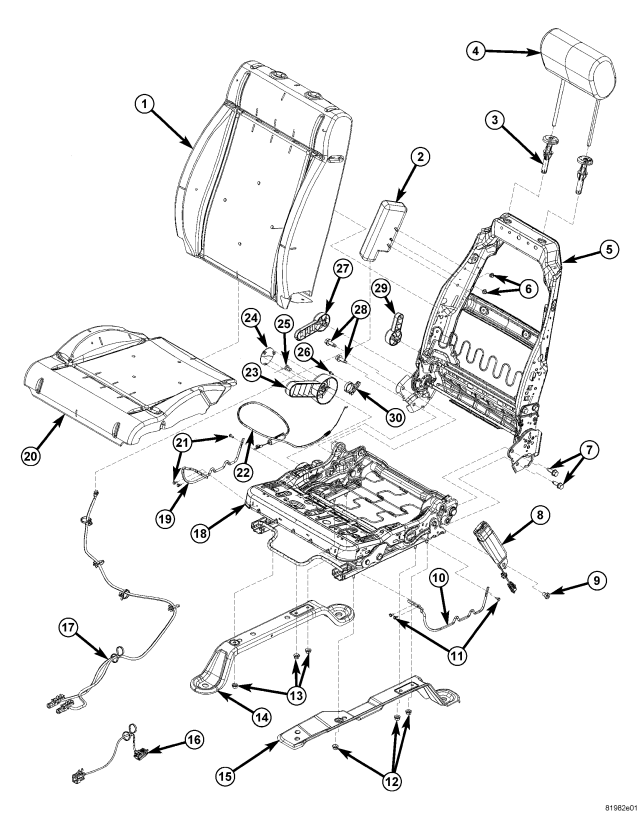
| RIGHT HAND SEAT – 4 WAY ADJUSTER |
| 1 - SEAT BACK CUSHION/COVER |
| 2 - SEAT AIR BAG |
| 3 - HEADREST SLEEVES |
| 4 - HEADREST |
| 5 - SEAT BACK FRAME |
| 6 - AIR BAG NUTS 7 N·m (5 ft. lbs.) |
| 7 - BACK ASSEMBLY BOLTS 47 N·m (34.5 ft. lbs.) |
| 8 - SEAT BELT BUCKLE |
| 9 - SEAT BELT BUCKLE BOLT 50 N·m (37 ft. lbs.) |
| 10 - TRIM ATTACHMENT WIRE |
| 11 - RIVETS |
| 12 - RISER NUTS 28 N·m (21 ft. lbs.) |
| 13 - RISER NUTS 28 N·m (21 ft. lbs.) |
| 14 - OUTBOARD RISER |
| 15 - INBOARD RISER |
| 16 - WIRE HARNESS |
| 17 - SIDE AIR BAG WIRE HARNESS |
| 18 - SEAT CUSHION FRAME |
| 19 - TRIM ATTACHMENT WIRE |
| 20 - SEAT CUSHION/COVER |
| 21 - RIVETS |
| 22 - EASY ENTRY CABLE |
| 23 - LIFT HANDLE |
| 24 - LIFT HANDLE CAP |
| 25 - LIFT HANDLE SCREW |
| 26 - SCREW |
| 27 - RECLINER HANDLE |
| 28 - BACK ASSEMBLY BOLTS 47 N·m (34.5 ft. lbs.) |
| 29 - EASY ENTRY HANDLE |
| 30 - EASY ENTRY CABLE ROUTER |
REMOVAL
1. Before proceeding with the following repair procedure, review all warnings and cautions. (Refer to 23 - BODY/SEATS - WARNING)
WARNING: The Seat Weight Sensor is a sensitive, calibrated unit and must be handled carefully. Do not drop or handle roughly. If dropped or damaged, replace with another sensor. Failure to follow these instructions may result in personal injury or death.
WARNING: The front passenger seat must be handled carefully as well. When removing the seat, be careful when setting on floor not to drop. If dropped, the sensor may be inoperative. Failure to follow these instructions may result in personal injury or death.
WARNING: When the seat is on the floor, no one should sit in the front passenger seat. This uneven force may damage the sensing ability of the seat weight sensors. If sat on and damaged, the sensor may be inoperative. Failure to follow these instructions may result in personal injury or death.
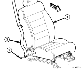
NOTE: If equipped with a traveling seat belt anchor.
2. Adjust the front seat (1) to its most forward position for easiest access to the front seat belt (3) lower anchor and the B-pillar trim.
3. Disconnect and isolate the battery negative cable. Wait two minutes for the system capacitor to discharge before further service.
4. Remove the screw (2) that secures the lower anchor to the outboard side of the front seat cushion frame.
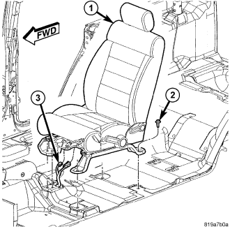
5. Remove the four seat bolts (2).
6. Tip the seat back and disconnect the electrical connectors (3).
7. Remove the seat.
INSTALLATION
1. Before proceeding with the following repair procedure, review all warnings and cautions. (Refer to 23 - BODY/SEATS - WARNING)
WARNING: The Seat Weight Sensor is a sensitive, calibrated unit and must be handled carefully. Do not drop or handle roughly. If dropped or damaged, replace with another sensor. Failure to follow these instructions may result in personal injury or death.
WARNING: The front passenger seat must be handled carefully as well. When removing the seat, be careful when setting on floor not to drop. If dropped, the sensor may be inoperative. Failure to follow these instructions may result in personal injury or death.
WARNING: When the seat is on the floor, no one should sit in the front passenger seat. This uneven force may damage the sensing ability of the seat weight sensors. If sat on and damaged, the sensor may be inoperative. Failure to follow these instructions may result in personal injury or death.
2. Position the seat into the vehicle and connect the electrical connectors (3), if equipped.
3. Install the bolts (2).
a. Adjust the seat rearward.
b. Tighten the front inboard bolt to 61 N·m (45 ft. lbs.).
c. Tighten the front outboard bolt to 61 N·m (45 ft. lbs.).
d. Adjust the seat forward.
e. Tighten the rear inboard bolt to 61 N·m (45 ft. lbs.).
f. Tighten the rear outboard bolt to 61 N·m (45 ft. lbs.).
NOTE: If equipped with a traveling seat belt anchor.
4. Position the seat belt (3) lower anchor to the mounting hole on the outboard side of the front seat (1) cushion frame. Be certain that the seat belt webbing between the turning loop and the lower anchor is not twisted.
5. Install and tighten the screw (2) that secures the lower anchor to the seat. Tighten the screw to 40 N·m (30 ft. lbs.).
6. Do not reconnect the battery negative cable at this time. The supplemental restraint system verification test procedure should be performed following service of any supplemental restraint system component. (Refer to 8 - ELECTRICAL/RESTRAINTS - STANDARD PROCEDURE - VERIFICATION TEST).