DIAGNOSIS AND TESTING
- C0077- LOW TIRE PRESSURE
- C1501-TIRE PRESSURE SENSOR 1 INTERNAL
- C1502-TIRE PRESSURE SENSOR 2 INTERNAL
- C1503-TIRE PRESSURE SENSOR 3 INTERNAL
- C1504-TIRE PRESSURE SENSOR 4 INTERNAL
- *STORED LOST COMMUNICATION DTC'S
C0077- LOW TIRE PRESSURE
For a complete wiring diagram Refer to Section 8W.
Theory of Operation
The Tire Pressure Monitoring System (TPMS) will warn the driver of a low tire pressure based on the vehicle recommended cold placard pressure. The tire pressure will vary with temperature by about 1 psi (6.9 kPa) for every 12°F (6.5°C). This means that when the outside temperature decreases, the tire pressure will decrease. Tire pressure should always be set based on cold inflation tire pressure. This is defined as the tire pressure after a vehicle has not been driven for more than 3 hours - and in outside ambient temperature. . The tire pressure will also increase as the vehicle is driven - this is normal and there should be no adjustment for this increased pressure. The TPM System will warn the driver of a low tire pressure if the tire pressure falls below the low pressure warning threshold for any reason, including low temperature effects. The TPM System will continue to warn the driver of low tire pressure as long as the condition exists, and will not turn off until the tire pressure is at or above recommended cold placard pressure. Once the low tire pressure warning has been illuminated, the tire pressure must be increased to the recommended cold placard pressure in order for the TPM warning lamp to be turned off. The system will automatically update and the TPM warning lamp will extinguish once the updated tire pressures have been received. The vehicle may need to be driven for up to 10 minutes above 15 mph (25 kph) to receive this information. Seasonal temperature changes will affect tire pressure, and the TPM system will monitor the actual tire pressure in the tire. For example, your vehicle may have a recommended cold (parked for more than 3 hours) placard of 30 (207 kPa). If the ambient temperature is 68°F (20°C) and the measured tire pressure is 27 psi (186 kPa), a temperature drop to 20°F (-7°C) will decrease the tire pressure to approximately 23 psi (157 kPa). This tire pressure is sufficiently low enough to turn ON the TPM lamp. Driving the vehicle may cause the tire pressure to rise to approximately 27 psi (186 kPa), but the TPM lamp will still be ON. In this situation, the TPM lamp will turn OFF only after the tires have been inflated to the vehicle’s recommended cold placard pressure value.
- When Monitored:
Continuously.
- Set Condition:
A low pressure condition will exist when the tire pressure falls below or is equal to the low pressure threshold value as specified for the vehicle.
| Possible Causes |
| INTERMITTENT PERFORMANCE DTC |
| INCORRECT PLACARD VALUES |
| INCORRECT TIRE PRESSURE |
| TIRE PRESSURE SENSOR |
| WCM (SKREEM) |
Diagnostic Test
1. DTC STATUS IS ACTIVENOTE: If the incorrect Placard Values were programmed into the WCM/SKREEM, a DTC could be set. Before continuing with any TPM diagnostic test, using the scan tool, check that the correct Placard Values have been programmed in to the module.
NOTE:
If the following conditions are present:
– Low Tire Pressure DTC (C0077) (Active)
– Spare Tire is not equipped with a Tire Pressure Sensor
– Spare Tire is currently on the vehicle
Repair the tire and place it back on the vehicle.
Test drive the vehicle.
If the DTC(s) reset continue with the diagnostic procedure.
Turn the ignition on.
With the scan tool, select View DTCs in the Wireless Control Module (SKREEM).
Is the DTC status Active at this time?
Yes
- Go to 2
No
- Go to 5
2. INCORRECT PLACARD VALUES
With the scan tool read the placard values programed in the WCM
Does the programed placard values equal the placard value on the vehicle?
Yes
- Go to 3
No
- Update placard pressure values in the WCM.
- Perform TPM VERIFICATION TEST. (Refer to 22 - TIRES/WHEELS/TIRE PRESSURE MONITORING - STANDARD PROCEDURE)
3. LOW TIRE PRESSURE
With the scan tool, clear DTCs in the Wireless Control Module (SKREEM).
With the scan tool, view tire pressure values.
Are all tire pressure values at or exceed placard values?
Yes
- Go to 4
No
- Fill all tires to placard pressure specifications.
- Perform TPM VERIFICATION TEST. (Refer to 22 - TIRES/WHEELS/TIRE PRESSURE MONITORING - STANDARD PROCEDURE)
4. TIRE PRESSURE SENSOR
NOTE: Before continuing, ensure the tire is free from any leaks or damage that would cause a low tire pressure condition. If a problem is found, repair as necessary and retest.
Turn the ignition off.
Replace the Tire Pressure Sensor in accordance with the Service Information.
With the scan tool, clear DTCs in the Wireless Control Module (SKREEM).
Test Drive the vehicle for a minimum of 10 minutes with vehicle speed greater than 15 MPH (24 km/h).
With the scan tool, select View DTCs in the Wireless Control Module (SKREEM).
Does the DTC reset or is the status Active for this DTC?
Yes
- Replace the Wireless Control Module (SKREEM) in accordance with the Service Information.
- Perform TPM VERIFICATION TEST. (Refer to 22 - TIRES/WHEELS - DIAGNOSIS AND TESTING)
No
- Test Complete.
- Perform TPM VERIFICATION TEST. (Refer to 22 - TIRES/WHEELS/TIRE PRESSURE MONITORING - STANDARD PROCEDURE)
5. INTERMITTENT TIRE PRESSURE SENSOR DTC
The conditions necessary to set this DTC are not present at this time.
Refer to any Technical Service Bulletins that may apply to this condition.
With the scan tool, clear DTCs in the Wireless Control Module (SKREEM).
Test Drive the vehicle for a minimum of 10 minutes with vehicle speed greater than 15 MPH (24 km/h).
With the scan tool, select View DTCs in the Wireless Control Module (SKREEM).
Does the DTC reset or is the status Active for this DTC?
Yes
- Repair as necessary.
- Perform TPM VERIFICATION TEST. (Refer to 22 - TIRES/WHEELS - DIAGNOSIS AND TESTING)
No
- Test complete.
- Perform TPM VERIFICATION TEST. (Refer to 22 - TIRES/WHEELS/TIRE PRESSURE MONITORING - STANDARD PROCEDURE)
C1501-TIRE PRESSURE SENSOR 1 INTERNAL
For a complete wiring diagram Refer to Section 8W
Theory of Operation
The tire pressure sensor actively monitors the air pressure and air temperature inside the tire, the sensor internal battery status, and the radial acceleration of the wheel. Each sensor has a unique ID code. The sensor transmits the data at regular intervals via an encoded signal to a receiver circuit located in the Wireless Control Module (SKREEM).
- When Monitored:
With vehicle speed greater than 15 MPH (24 km/h).
- Set Condition:
The WCM (SKREEM) will monitor the signals from the four active road tire sensors. A loss of signal error is detected when eight consecutive blocks of data are not received or cannot be accurately decoded within a maximum period of 10 minutes. An internal sensor hardware error condition will be set when an error in the accelerometer, pressure sensor, or temperature sensor is detected.
| Possible Causes |
| WRONG SENSOR |
| TEMPORARY SPARE TIRE IN USE |
| OUTSIDE INTERFERENCE |
| TIRE PRESSURE SENSOR |
| WIRELESS CONTROL MODULE (SKREEM) |
Diagnostic Test
1. DTC STATUS IS ACTIVENOTE:
If the following conditions are present:
– Tire Pressure Sensor Internal DTC (Active)
– Spare Tire is not equipped with a Tire Pressure Sensor
– Spare Tire is currently on the vehicle
Repair the tire and place it back on the vehicle .
Test drive the vehicle.
If the DTC(s) reset continue with the diagnostic procedure.
Turn the ignition on.
With the scan tool, select View DTCs in the Wireless Control Module (SKREEM).
Is the DTC status Active at this time?
Yes
- Go to 2
No
- Go to 4
2. TIRE PRESSURE SENSOR
NOTE:
When working with vehicles equipped with the base tire pressure monitoring system the correct tire that set the fault must be identified. Following the below procedure will help in identifying the correct tire.
1. Set all tire pressures to the recommended specifications and recheck for fault/alert.
2. Turn the ignition on.
3. Starting with the left front wheel, deflate the tire to 20 PSI and wait 2 minutes. The fault will set once the pressure has reached 20 PSI within the 2 minute time frame.
4. If the TPM fault was detected and not associated to this Sensor/Transmitter, repeat the process until the faulty Sensor/Transmitter has been identified.
Once a fault/alert has set, it will establish the location of the tire pressure sensor/transmitter. Repeat steps until the applicable Tire Pressure Sensor/Transmitter has been located.Turn the ignition off.
Replace the Tire Pressure Sensor in accordance with the Service Information.
With the scan tool, clear DTCs in the Wireless Control Module (SKREEM).
Test Drive the vehicle for a minimum of 10 minutes with vehicle speed greater than 15 MPH (24 km/h).
With the scan tool, select View DTCs in the Wireless Control Module (SKREEM).
Does the DTC reset or is the status Active for this DTC?
Yes
- Go to 3
No
- Test Complete.
- Perform TPM VERIFICATION TEST. (Refer to 22 - TIRES/WHEELS/TIRE PRESSURE MONITORING - STANDARD PROCEDURE)
3. WIRELESS CONTROL MODULE (SKREEM)
View repair.
Repair
- Replace the Wireless Control Module (SKREEM) in accordance with the Service Information.
- Perform TPM VERIFICATION TEST. (Refer to 22 - TIRES/WHEELS/TIRE PRESSURE MONITORING - STANDARD PROCEDURE)
4. INTERMITTENT TIRE PRESSURE SENSOR DTC
The conditions necessary to set this DTC are not present at this time.
Refer to any Technical Service Bulletins that may apply to this condition.
With the scan tool, clear DTCs in the Wireless Control Module (SKREEM).
Test Drive the vehicle for a minimum of 10 minutes with vehicle speed greater than 15 MPH (24 km/h).
With the scan tool, select View DTCs in the Wireless Control Module (SKREEM).
Does the DTC reset or is the status Active for this DTC?
Yes
- Return to the beginning of this test and perform the diagnostic procedure as necessary.
No
- Test complete.
- Perform TPM VERIFICATION TEST. (Refer to 22 - TIRES/WHEELS/TIRE PRESSURE MONITORING - STANDARD PROCEDURE)
C1502-TIRE PRESSURE SENSOR 2 INTERNAL
For a complete wiring diagram Refer to Section 8W
Theory of Operation
The tire pressure sensor actively monitors the air pressure and air temperature inside the tire, the sensor internal battery status, and the radial acceleration of the wheel. Each sensor has a unique ID code. The sensor transmits the data at regular intervals via an encoded signal to a receiver circuit located in the Wireless Control Module (SKREEM).
- When Monitored:
With vehicle speed greater than 15 MPH (24 km/h).
- Set Condition:
The WCM (SKREEM) will monitor the signals from the four active road tire sensors. A loss of signal error is detected when eight consecutive blocks of data are not received or cannot be accurately decoded within a maximum period of 10 minutes. An internal sensor hardware error condition will be set when an error in the accelerometer, pressure sensor, or temperature sensor is detected.
| Possible Causes |
| INTERMITTENT TIRE PRESSURE SENSOR INTERNAL DTC |
| SPARE TIRE IN USE |
| TIRE PRESSURE SENSOR |
| WIRELESS CONTROL MODULE (SKREEM) |
Diagnostic Test
1. DTC STATUS IS ACTIVENOTE:
If the following conditions are present:
– Tire Pressure Sensor Internal DTC (Active)
– Spare Tire is not equipped with a Tire Pressure Sensor
– Spare Tire is currently on the vehicle
Repair the tire and place it back on the vehicle.
Test drive the vehicle.
If the DTC(s) reset continue with the diagnostic procedure.
Turn the ignition on.
With the scan tool, select View DTCs in the Wireless Control Module (SKREEM).
Is the DTC status Active at this time?
Yes
- Go to 2
No
- Go to 4
2. TIRE PRESSURE SENSOR
NOTE:
When working with vehicles equipped with the base tire pressure monitoring system the correct tire that set the fault must be identified. Following the below procedure will help in identifying the correct tire.
1. Set all tire pressures to the recommended specifications and recheck for fault/alert.
2. Turn the ignition on.
3. Starting with the left front wheel, deflate the tire to 20 PSI and wait 2 minutes. The fault will set once the pressure has reached 20 PSI within the 2 minute time frame.
4. If the TPM fault was detected and not associated to this Sensor/Transmitter, repeat the process until the faulty Sensor/Transmitter has been identified.
Once a fault/alert has set, it will establish the location of the tire pressure sensor/transmitter. Repeat steps until the applicable Tire Pressure Sensor/Transmitter has been located.Turn the ignition off.
Replace the Tire Pressure Sensor in accordance with the Service Information.
With the scan tool, clear DTCs in the Wireless Control Module (SKREEM).
Test Drive the vehicle for a minimum of 10 minutes with vehicle speed greater than 15 MPH (24 km/h).
With the scan tool, select View DTCs in the Wireless Control Module (SKREEM).
Does the DTC reset or is the status Active for this DTC?
Yes
- Go to 3
No
- Test Complete.
- Perform TPM VERIFICATION TEST. (Refer to 22 - TIRES/WHEELS/TIRE PRESSURE MONITORING - STANDARD PROCEDURE)
3. WIRELESS CONTROL MODULE (SKREEM)
View repair.
Repair
- Replace the Wireless Control Module (SKREEM) in accordance with the Service Information.
- Perform TPM VERIFICATION TEST. (Refer to 22 - TIRES/WHEELS/TIRE PRESSURE MONITORING - STANDARD PROCEDURE)
4. INTERMITTENT TIRE PRESSURE SENSOR DTC
The conditions necessary to set this DTC are not present at this time.
Refer to any Technical Service Bulletins that may apply to this condition.
With the scan tool, clear DTCs in the Wireless Control Module (SKREEM).
Test Drive the vehicle for a minimum of 10 minutes with vehicle speed greater than 15 MPH (24 km/h).
With the scan tool, select View DTCs in the Wireless Control Module (SKREEM).
Does the DTC reset or is the status Active for this DTC?
Yes
- Return to the beginning of this test and perform the diagnostic procedure as necessary.
No
- Test complete.
- Perform TPM VERIFICATION TEST. (Refer to 22 - TIRES/WHEELS/TIRE PRESSURE MONITORING - STANDARD PROCEDURE)
C1503-TIRE PRESSURE SENSOR 3 INTERNAL
For a complete wiring diagram Refer to Section 8W
Theory of Operation
The tire pressure sensor actively monitors the air pressure and air temperature inside the tire, the sensor internal battery status, and the radial acceleration of the wheel. Each sensor has a unique ID code. The sensor transmits the data at regular intervals via an encoded signal to a receiver circuit located in the Wireless Control Module (SKREEM).
- When Monitored:
With vehicle speed greater than 15 MPH (24 km/h).
- Set Condition:
The WCM (SKREEM) will monitor the signals from the four active road tire sensors. A loss of signal error is detected when eight consecutive blocks of data are not received or cannot be accurately decoded within a maximum period of 10 minutes. An internal sensor hardware error condition will be set when an error in the accelerometer, pressure sensor, or temperature sensor is detected.
| Possible Causes |
| INTERMITTENT TIRE PRESSURE SENSOR INTERNAL DTC |
| SPARE TIRE IN USE |
| TIRE PRESSURE SENSOR |
| WIRELESS CONTROL MODULE (SKREEM) |
Diagnostic Test
1. DTC STATUS IS ACTIVENOTE:
If the following conditions are present:
– Tire Pressure Sensor Internal DTC (Active)
– Spare Tire is not equipped with a Tire Pressure Sensor
– Spare Tire is currently on the vehicle
Repair the tire and place it back on the vehicle.
Test drive the vehicle.
If the DTC(s) reset continue with the diagnostic procedure.
Turn the ignition on.
With the scan tool, select View DTCs in the Wireless Control Module (SKREEM).
Is the DTC status Active at this time?
Yes
- Go to 2
No
- Go to 4
2. TIRE PRESSURE SENSOR
NOTE:
When working with vehicles equipped with the base tire pressure monitoring system the correct tire that set the fault must be identified. Following the below procedure will help in identifying the correct tire.
1. Set all tire pressures to the recommended specifications and recheck for fault/alert.
2. Turn the ignition on.
3. Starting with the left front wheel, deflate the tire to 20 PSI and wait 2 minutes. The fault will set once the pressure has reached 20 PSI within the 2 minute time frame.
4. If the TPM fault was detected and not associated to this Sensor/Transmitter, repeat the process until the faulty Sensor/Transmitter has been identified.
Once a fault/alert has set, it will establish the location of the tire pressure sensor/transmitter. Repeat steps until the applicable Tire Pressure Sensor/Transmitter has been located.Turn the ignition off.
Replace the Tire Pressure Sensor in accordance with the Service Information.
With the scan tool, clear DTCs in the Wireless Control Module (SKREEM).
Test Drive the vehicle for a minimum of 10 minutes with vehicle speed greater than 15 MPH (24 km/h).
With the scan tool, select View DTCs in the Wireless Control Module (SKREEM).
Does the DTC reset or is the status Active for this DTC?
Yes
- Go to 3
No
- Test Complete.
- Perform TPM VERIFICATION TEST. (Refer to 22 - TIRES/WHEELS/TIRE PRESSURE MONITORING - STANDARD PROCEDURE)
3. WIRELESS CONTROL MODULE (SKREEM)
View repair.
Repair
- Replace the Wireless Control Module (SKREEM) in accordance with the Service Information.
- Perform TPM VERIFICATION TEST. (Refer to 22 - TIRES/WHEELS/TIRE PRESSURE MONITORING - STANDARD PROCEDURE)
4. INTERMITTENT TIRE PRESSURE SENSOR DTC
The conditions necessary to set this DTC are not present at this time.
Refer to any Technical Service Bulletins that may apply to this condition.
With the scan tool, clear DTCs in the Wireless Control Module (SKREEM).
Test Drive the vehicle for a minimum of 10 minutes with vehicle speed greater than 15 MPH (24 km/h).
With the scan tool, select View DTCs in the Wireless Control Module (SKREEM).
Does the DTC reset or is the status Active for this DTC?
Yes
- Return to the beginning of this test and perform the diagnostic procedure as necessary.
No
- Test complete.
- Perform TPM VERIFICATION TEST. (Refer to 22 - TIRES/WHEELS/TIRE PRESSURE MONITORING - STANDARD PROCEDURE)
C1504-TIRE PRESSURE SENSOR 4 INTERNAL
For a complete wiring diagram Refer to Section 8W
Theory of Operation
The tire pressure sensor actively monitors the air pressure and air temperature inside the tire, the sensor internal battery status, and the radial acceleration of the wheel. Each sensor has a unique ID code. The sensor transmits the data at regular intervals via an encoded signal to a receiver circuit located in the Wireless Control Module (SKREEM).
- When Monitored:
With vehicle speed greater than 15 m.p.h. (24 km/h).
- Set Condition:
The WCM (SKREEM) will monitor the signals from the four active road tire sensors. A loss of signal error is detected when eight consecutive blocks of data are not received or cannot be accurately decoded within a maximum period of 10 minutes. An internal sensor hardware error condition will be set when an error in the accelerometer, pressure sensor, or temperature sensor is detected.
| Possible Causes |
| INTERMITTENT TIRE PRESSURE SENSOR INTERNAL DTC |
| SPARE TIRE IN USE |
| TIRE PRESSURE SENSOR |
| WIRELESS CONTROL MODULE (SKREEM) |
Diagnostic Test
1. DTC STATUS IS ACTIVENOTE:
If the following conditions are present:
– Tire Pressure Sensor Internal DTC (Active)
– Spare Tire is not equipped with a Tire Pressure Sensor
– Spare Tire is currently on the vehicle
Repair the tire and place it back on the vehicle.
Test drive the vehicle.
If the DTC(s) reset continue with the diagnostic procedure.
Turn the ignition on.
With the scan tool, select View DTCs in the Wireless Control Module (SKREEM).
Is the DTC status Active at this time?
Yes
- Go to 2
No
- Go to 4
2. TIRE PRESSURE SENSOR
NOTE:
When working with vehicles equipped with the base tire pressure monitoring system the correct tire that set the fault must be identified. Following the below procedure will help in identifying the correct tire.
1. Set all tire pressures to the recommended specifications and recheck for fault/alert.
2. Turn the ignition on.
3. Starting with the left front wheel, deflate the tire to 20 PSI and wait 2 minutes. The fault will set once the pressure has reached 20 PSI within the 2 minute time frame.
4. If the TPM fault was detected and not associated to this Sensor/Transmitter, repeat the process until the faulty Sensor/Transmitter has been identified.
Once a fault/alert has set, it will establish the location of the tire pressure sensor/transmitter. Repeat steps until the applicable Tire Pressure Sensor/Transmitter has been located.Turn the ignition off.
Replace the Tire Pressure Sensor in accordance with the Service Information.
With the scan tool, clear DTCs in the Wireless Control Module (SKREEM).
Test Drive the vehicle for a minimum of 10 minutes with vehicle speed greater than 15 m.p.h.
With the scan tool, select View DTCs in the Wireless Control Module (SKREEM).
Does the DTC reset or is the status Active for this DTC?
Yes
- Go to 3
No
- Test Complete.
- Perform TPM VERIFICATION TEST. (Refer to 22 - TIRES/WHEELS/TIRE PRESSURE MONITORING - STANDARD PROCEDURE)
3. WIRELESS CONTROL MODULE (SKREEM)
View repair.
Repair
- Replace the Wireless Control Module (SKREEM) in accordance with the Service Information.
- Perform TPM VERIFICATION TEST. (Refer to 22 - TIRES/WHEELS/TIRE PRESSURE MONITORING - STANDARD PROCEDURE)
4. INTERMITTENT TIRE PRESSURE SENSOR DTC
The conditions necessary to set this DTC are not present at this time.
Refer to any Technical Service Bulletins that may apply to this condition.
With the scan tool, clear DTCs in the Wireless Control Module (SKREEM).
Test Drive the vehicle for a minimum of 10 minutes with vehicle speed greater than 15 MPH (24 km/h).
With the scan tool, select View DTCs in the Wireless Control Module (SKREEM).
Does the DTC reset or is the status Active for this DTC?
Yes
- Return to the beginning of this test and perform the diagnostic procedure as necessary.
No
- Test complete.
- Perform TPM VERIFICATION TEST. (Refer to 22 - TIRES/WHEELS/TIRE PRESSURE MONITORING - STANDARD PROCEDURE)
*STORED LOST COMMUNICATION DTC'S
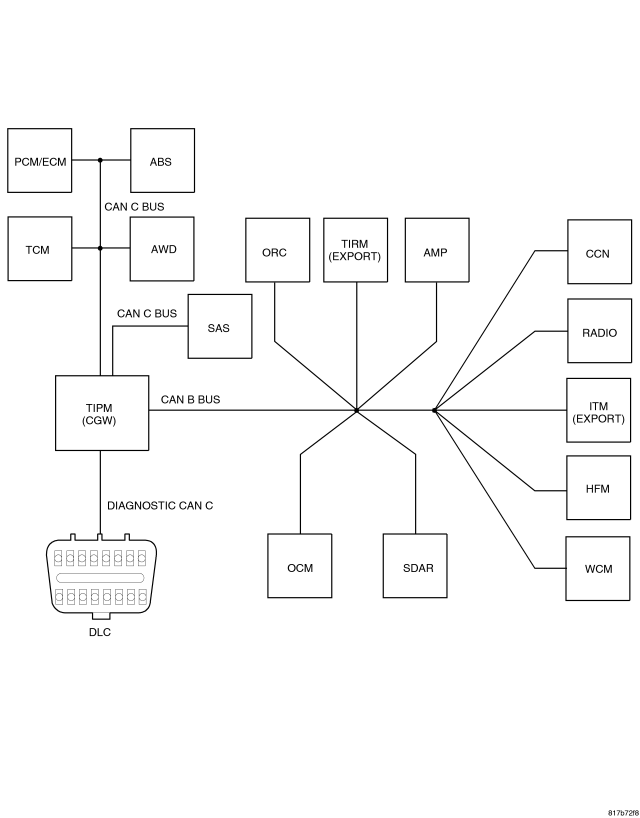
For a complete wiring diagram Refer to Section 8W.
- When Monitored:
With the ignition on.
Battery voltage between 10 and 16 volts.
IOD fuse installed.
TIPM is configured correctly.
- Set Condition:
Bus messages not received for approximately 2 to 5 seconds.
| Possible Causes |
| CAN B BUS CIRCUITS OPEN OR SHORTED |
| CAN C BUS CIRCUITS OPEN OR SHORTED |
| DTCS RELATED TO BATTERY VOLTAGE, IGNITION, OR VIN MESSAGES |
| TIPM NOT CONFIGURED CORRECTLY |
| POWER OR GROUND FROM THE REPORTING MODULE |
| MODULE THAT SET THIS DTC |
| PREVIOUS SERVICE PERFORMED WITHIN THE LAST 100 KEY CYCLES (FUSE/RELAYS REMOVED, WIRING SERVICE, BATTERY DISCONNECT) |
| LOW BATTERY/JUMP START CONDITION |
| IOD FUSE WAS REMOVED DURING SHIPPING |
| CHECK FOR RELATED TSB'S |
Diagnostic Test
1. VERIFY DTC IS STOREDNOTE: Stored faults may indicate a customer perceived intermittent condition.
NOTE: Ensure the IOD fuse is installed and battery voltage is between 10 and 16 volts before proceeding.
NOTE: Check for any TSB(s) related to the condition. If a TSB applies, perform the procedure outlined in the TSB before continuing.
With the scan tool, read stored DTC's.
Is this DTC stored?
Yes
- Go To 2
No
- Diagnose the active DTC. Refer to the Table of Contents for a list of the symptoms.
2. CHECK THE ENVIRONMENTAL DATA
With the scan tool, read the loss of communication environmental data.
Does the loss of communication environmental odometer data match up to any of the previous service procedures listed in the possible causes or are there any stored CAN B or C hardware electrical, battery, ignition voltage, VIN missing/mismatch, TIPM configuration DTC's present with matching environmental data?
Yes
- These DTC's may have been the result of other service procedures performed. Clear DTC's.
No
- Go To 3
3. VERIFY INTERMITTENT LOST COMMUNICATION DTC – WIRING CONCERNS
Turn the ignition on.
With the scan tool, select Network View and select Advanced.
Is there more than one ECU with stored DTC's “Logged Against” the module and one or more lost communication DTC's stored in the offending module?
Yes
- Verify if the vehicle was recently in for this type of service. Otherwise, visually inspect the related wiring harness for chafed, pierced, pinched, and partially broken wires and the wiring harness connectors for broken, bent, pushed out, and corroded terminals. Repair as necessary.
No
- Go To 4
4. VERIFY INTERMITTENT LOST COMMUNICATION DTC – OFFENDING MODULE
Turn the ignition on.
With the scan tool, select Network View and select Advanced.
Is there more than one ECU with stored DTC's “Logged Against” the module and NO lost communication DTC's stored in the offending module?
Yes
- Check for TSB(s) related to this offending module.
No
- Go To 5
5. VERIFY INTERMITTENT LOST COMMUNICATION DTC – REPORTING MODULE
Turn the ignition on.
With the scan tool, select Network View and select Advanced.
Is there ONLY ONE ECU with stored DTC's “Logged Against” the module?
Yes
- Check for TSB(s) related to the module that set this DTC.
No
- Verify if the vehicle was recently in for this type of service. Otherwise, visually inspect the related wiring harness for chafed, pierced, pinched, and partially broken wires and the wiring harness connectors for broken, bent, pushed out, and corroded terminals. Repair as necessary.