STANDARD PROCEDURE
STANDARD PROCEDURE - VALVE TIMING VERIFICATION
1. Remove front cylinder head cover and all 6 spark plugs.
2. Rotate engine until the #2 piston is at TDC of the compression stroke.
3. Install a degree wheel on the crankshaft pulley.
4. With proper adaptor, install a dial indicator into #2 spark plug hole. Using the indicator find TDC on the compression stroke.
5. Position the degree wheel to zero.
6. Remove dial indicator from spark plug hole.
7. Place a 5.08 mm (0.200 in.) spacer between the valve stem tip of #2 intake valve and rocker arm pad. Allow tappet to bleed down to give a solid tappet effect.
8. Install a dial indicator so plunger contacts the #2 intake valve spring retainer as nearly perpendicular as possible. Zero the indicator.
9. Rotate the engine clockwise until the intake valve has lifted .254 mm (0.010 in.).
CAUTION: Do not turn crankshaft any further clockwise as intake valve might bottom and result in serious damage.
10. Degree wheel should read 6 degrees BTDC to 6 degrees ATDC.
STANDARD PROCEDURE - MEASURING TIMING CHAIN WEAR
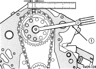
1. Position a scale next to timing chain so that any movement of chain may be measured.
2. Position a torque wrench and socket on the camshaft sprocket attaching bolt. Apply force in the direction of crankshaft rotation to take up slack to the following torque:
- 41 N·m (30 ft. lb.) with cylinder heads installed
- 20 N·m (15 ft. lb.) with cylinder heads removed
NOTE: With torque applied to the camshaft sprocket bolt, crankshaft should not be permitted to move. It may be necessary to block crankshaft to prevent rotation.
3. Holding a measuring scale along edge of chain links.
4. Apply force in the reverse direction to the following torque:
- 41 N·m (30 ft. lb.) with cylinder heads installed
- 20 N·m (15 ft. lb.) with cylinder heads removed
5. Measure amount of sprocket/chain movement.
6. Install a new timing chain and sprockets if movement exceeds 3.175 mm (1/8 in.).