INTRUSION MODULE - EXPORT
DESCRIPTION
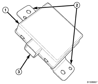
An intrusion module (1) is part of the premium version of the Vehicle Theft Alarm (VTA) in the Vehicle Theft Security System (VTSS). The premium version of the VTA is only available in vehicles built for certain markets, where the additional features offered by this system are required. The intrusion module is located under the instrument panel within the passenger compartment. This unit is designed to work in conjunction with the remote microwave intrusion sensor transducers to provide interior motion detection and serves as an interface between the Totally Integrated Power Module (TIPM), the ElectroMechanical Instrument Cluster (EMIC) (also known as the Cab Compartment Node/CCN) and the alarm siren.
The molded plastic intrusion module housing has two integral mounts (2) that secure the module with two screws to U-nuts on a stamped steel mounting bracket. The mounting bracket is secured with two additional U-nuts and screws to the lower instrument panel reinforcement behind the steering column opening cover under the driver side instrument panel. Concealed within the module housing is the electronic circuitry of the module, which includes a microprocessor. The module is connected to the vehicle electrical system through an integral connector receptacle (3) by a dedicated take out and connector of the instrument panel wire harness.
The intrusion module unit cannot be adjusted or repaired and, if ineffective or damaged, it must be replaced.
OPERATION
The microprocessor in the intrusion module controls all of the features of the export premium version of the Vehicle Theft Alarm (VTA). The module uses On-Board Diagnostics (OBD) and can communicate with other electronic modules in the vehicle as well as with a diagnostic scan tool using the Controller Area Network (CAN) data bus. This method of communication is used by the module to communicate with the Totally Integrated Power Module (TIPM) and for diagnosis and testing through the 16-way data link connector located on the driver side lower edge of the instrument panel. The intrusion module also communicates with the alarm siren module and the remote intrusion sensors over dedicated serial bus circuits.
The intrusion module microprocessor continuously monitors inputs from the two (two-door vehicles) or three (four-door vehicles) microwave intrusion sensor transducers as well as inputs from the TIPM and the alarm siren module. The module energizes the intrusion sensors when the system is armed, then monitors inputs from the sensors related to both motion detection and to detect problems with the sensors or sensor circuits. If an object is moving in the interior, a detection circuit in the intrusion sensor senses this movement through the modulation of the returning microwave signals that occurs due to the Doppler effect. The motion detection function of the intrusion module can be disabled by depressing the LOCK button on the Remote Keyless Entry (RKE) transmitter three times within 15 seconds while the VTA is arming (security indicator is flashing rapidly). The intrusion module will signal the alarm siren module to provide a single siren chirp as an audible confirmation that the motion sensor function has been disabled.
If movement is detected while the VTA is armed, the intrusion module sends an electronic status message to the TIPM over the CAN data bus to flash the exterior lighting, and sends an electronic message to the alarm siren module over a dedicated serial bus line to sound the siren. When the TIPM detects a breach in the perimeter protection through a hard wired door, swing gate or hood ajar switch input, it sends an electronic message to the intrusion module and the module sends an electronic message to the alarm siren over a dedicated serial bus line to sound the siren.
The intrusion module also monitors inputs from the alarm siren module for siren battery or siren input/output circuit tamper alerts, and for siren battery condition alerts, then sets active and stored Diagnostic Trouble Codes (DTC) for any monitored system faults it detects. An active fault only remains for the current ignition switch cycle, while a stored fault causes a DTC to be stored in memory by the intrusion module. If a fault does not recur for 50 ignition cycles, the module will automatically erase the stored DTC.
The intrusion module is connected to the vehicle electrical system through the instrument panel wire harness. The module receives battery current through a fuse in the TIPM, and receives ground through the instrument panel wire harness. These connections allow the module to remain operational, regardless of the ignition switch position.
The hard wired circuits of the intrusion module may be diagnosed using conventional diagnostic tools and procedures. Refer to the appropriate wiring information. However, conventional diagnostic methods will not prove conclusive in the diagnosis of the intrusion module or the electronic controls or communication between modules and other devices that provide some features of the VTA. The most reliable, efficient, and accurate means to diagnose the intrusion module or the electronic controls and communication related to intrusion module operation requires the use of a diagnostic scan tool. Refer to the appropriate diagnostic information.
REMOVAL
WARNING: To avoid serious or fatal injury on vehicles equipped with airbags, disable the supplemental restraint system before attempting any steering wheel, steering column, airbag, occupant classification system, seat belt tensioner, impact sensor, or instrument panel component diagnosis or service. Disconnect and isolate the battery negative (ground) cable, then wait two minutes for the system capacitor to discharge before performing further diagnosis or service. This is the only sure way to disable the supplemental restraint system. Failure to take the proper precautions could result in accidental airbag deployment.
1. Disconnect and isolate the battery negative cable.
2. Remove the steering column opening cover from the instrument panel. (Refer to 23 - BODY/INSTRUMENT PANEL/STEERING COLUMN OPENING COVER - REMOVAL).
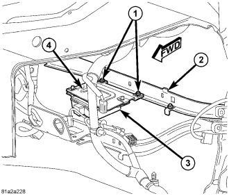
3. Remove the two screws (1) that secure the intrusion module mounting bracket (4) to the lower instrument panel reinforcement (2).
4. Lower the intrusion module (3) and mounting bracket from the instrument panel reinforcement far enough to access and disconnect the instrument panel wire harness connector from the connector receptacle at the forward-facing end of the module housing.
5. Remove the module and mounting bracket from under the instrument panel as a unit.
INSTALLATION
WARNING: To avoid serious or fatal injury on vehicles equipped with airbags, disable the supplemental restraint system before attempting any steering wheel, steering column, airbag, occupant classification system, seat belt tensioner, impact sensor, or instrument panel component diagnosis or service. Disconnect and isolate the battery negative (ground) cable, then wait two minutes for the system capacitor to discharge before performing further diagnosis or service. This is the only sure way to disable the supplemental restraint system. Failure to take the proper precautions could result in accidental airbag deployment.
1. Position the intrusion module (3) and mounting bracket (4) under the instrument panel as a unit.
2. Reconnect the instrument panel wire harness connector to the connector receptacle at the forward-facing of the module housing.
3. Position the module mounting bracket to the lower instrument panel reinforcement (2).
4. Install and tighten the two screws (1) that secure the mounting bracket to the lower instrument panel reinforcement. Tighten the screws to 8 N·m (71 in. lbs.).
5. Reinstall the steering column opening cover onto the instrument panel. (Refer to 23 - BODY/INSTRUMENT PANEL/STEERING COLUMN OPENING COVER - INSTALLATION).
6. Reconnect the battery negative cable.