DIAGNOSIS AND TESTING
- B2304-WIPER PARK SWITCH INPUT CIRCUIT LOW (STUCK LOW)
- B2305-WIPER PARK SWITCH INPUT CIRCUIT HIGH (STUCK HIGH)
- B230D-REAR WIPER PARK SWITCH INPUT CIRCUIT LOW (STUCK LOW)
- B230E-REAR WIPER PARK SWITCH INPUT CIRCUIT HIGH (STUCK HIGH)
- B2323-HEADLAMP WASHER MOTOR CONTROL CIRCUIT LOW
- B2324-HEADLAMP WASHER MOTOR CONTROL CIRCUIT HIGH
- B2376-REAR WIPER SWITCH INPUT CIRCUIT
B2304-WIPER PARK SWITCH INPUT CIRCUIT LOW (STUCK LOW)
For a complete wiring diagram Refer to Section 8W.
- When Monitored:
With the ignition on.
- Set Condition:
The Totally Integrated Power Module (TIPM) detects a short to ground on the Wiper Park Switch Sense circuit.
| Possible Causes |
| (W7) WIPER PARK SWITCH SENSE CIRCUIT SHORT TO GROUND |
| FRONT WIPER MOTOR |
| TOTALLY INTEGRATED POWER MODULE |
Diagnostic Test
1. INTERMITTENT CONDITIONTurn the ignition on.
With the scan tool, clear all DTC's.
Cycle the Wiper Switch on and off 3 times.
With the scan tool, read DTC's.
Does the scan tool display this DTC as active?
Yes
- Go To 2
No
- The condition that caused this symptom is currently not present. Check for an intermittent condition by inspecting the related wiring harness for chafed, pierced, pinched, and partially broken wires. Also, inspect the related connectors for broken, bent, pushed out, spread, corroded, or contaminated terminals. Repair as necessary.
- Perform the BODY VERIFICATION TEST — VER 1. (Refer to 8 - ELECTRICAL/ELECTRONIC CONTROL MODULES - STANDARD PROCEDURE)
2. FRONT WIPER MOTOR
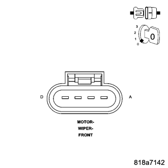
Turn the ignition off.
Disconnect the Front Wiper Motor harness connector.
Turn the ignition on.
Wait 30 seconds.
With the scan tool, read the Front Wiper Park Switch Sense.
Does the Front Wiper Park Switch Sense display: False?
Yes
- Replace the Front Wiper Motor in accordance with the Service Information.
- Perform the BODY VERIFICATION TEST — VER 1. (Refer to 8 - ELECTRICAL/ELECTRONIC CONTROL MODULES - STANDARD PROCEDURE)
No
- Go To 3
3. CHECK (W7) WIPER PARK SWITCH SENSE CIRCUIT FOR A SHORT TO GROUND
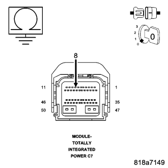
Turn the ignition off.
Disconnect the TIPM C7 harness connector.
Measure the resistance between ground and the (W7) Wiper Park Sense Circuit.
Is the resistance above 10k ohms?
Yes
- Replace the Totally Integrated Power Module (TIPM) in accordance with the Service Information.
- Perform the BODY VERIFICATION TEST — VER 1. (Refer to 8 - ELECTRICAL/ELECTRONIC CONTROL MODULES - STANDARD PROCEDURE)
No
- Repair the (W7) Wiper Park Switch Sense circuit for a short to ground.
- Perform the BODY VERIFICATION TEST — VER 1. (Refer to 8 - ELECTRICAL/ELECTRONIC CONTROL MODULES - STANDARD PROCEDURE)
B2305-WIPER PARK SWITCH INPUT CIRCUIT HIGH (STUCK HIGH)
For a complete wiring diagram Refer to Section 8W.
- When Monitored:
With the ignition on.
- Set Condition:
The Totally Integrated Power Module (TIPM) does not detect a change from High to Low voltage on the Wiper Park Switch Sense Circuit.
| Possible Causes |
| (W7) WIPER PARK SWITCH SENSE CIRCUIT OPEN |
| (W7) WIPER PARK SWITCH SENSE CIRCUIT SHORTED TO VOLTAGE |
| FRONT WIPER MOTOR |
| TOTALLY INTEGRATED POWER MODULE |
Diagnostic Test
1. INTERMITTENT CONDITIONTurn the ignition on.
With the scan tool, clear all DTC's.
Cycle the Wiper Switch on and off 3 times.
With the scan tool, read DTC's.
Does the scan tool display this DTC as active?
Yes
- Go To 2
No
- The condition that caused this symptom is currently not present. Check for an intermittent condition by inspecting the related wiring harness for chafed, pierced, pinched, and partially broken wires. Also, inspect the related connectors for broken, bent, pushed out, spread, corroded, or contaminated terminals. Repair as necessary.
- Perform the BODY VERIFICATION TEST — VER 1. (Refer to 8 - ELECTRICAL/ELECTRONIC CONTROL MODULES - STANDARD PROCEDURE)
2. (W7) WIPER PARK SWITCH SENSE CIRCUIT SHORTED TO VOLTAGE
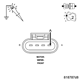
Turn the ignition off.
Disconnect the Front Wiper Motor harness connector.
Turn the ignition on.
Using a 12–volt test light connected to ground, probe the (W7) Wiper Park Switch Sense circuit.
Does the test light illuminate brightly?
Yes
- Repair the (W7) Wiper Park Switch Sense circuit for a short to voltage.
- Perform the BODY VERIFICATION TEST — VER 1. (Refer to 8 - ELECTRICAL/ELECTRONIC CONTROL MODULES - STANDARD PROCEDURE)
No
- Go To 3
3. CHECK THE FRONT WIPER MOTOR
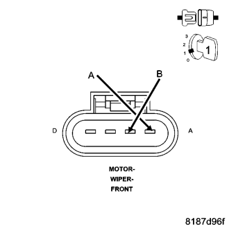
Connect a jumper wire between the (W7) Wiper Park Switch Sense circuit and ground.
With the scan tool, read the Front Wiper Park Switch Sense.
Does the Front Wiper Park Switch Sense display: True?
Yes
- Replace the Front Wiper Motor in accordance with the Service Information.
- Perform the BODY VERIFICATION TEST — VER 1. (Refer to 8 - ELECTRICAL/ELECTRONIC CONTROL MODULES - STANDARD PROCEDURE)
No
- Go To 4
4. CHECK (W7) WIPER PARK SWITCH SENSE CIRCUIT FOR AN OPEN
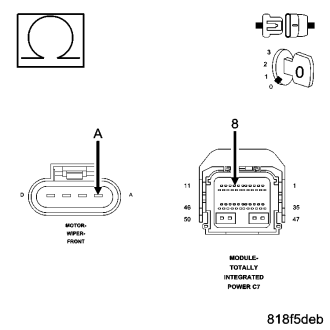
Turn the ignition off.
Disconnect the TIPM C7 harness connector.
Measure the resistance of the (W7) Wiper Park Switch Sense circuit between the Front Wiper Motor harness connector and the TIPM C7 harness connector.
Is the resistance below 10.0 ohms?
Yes
- Replace the Totally Integrated Power Module (TIPM) in accordance with the Service Information.
- Perform the BODY VERIFICATION TEST — VER 1. (Refer to 8 - ELECTRICAL/ELECTRONIC CONTROL MODULES - STANDARD PROCEDURE)
No
- Repair the (W7) Wiper Park Switch Sense circuit for an open.
- Perform the BODY VERIFICATION TEST - VER 1. (Refer to 8 - ELECTRICAL/ELECTRONIC CONTROL MODULES - STANDARD PROCEDURE)
B230D-REAR WIPER PARK SWITCH INPUT CIRCUIT LOW (STUCK LOW)
For a complete wiring diagram Refer to Section 8W.
- When Monitored:
With the ignition on.
- Set Condition:
The Totally Integrated Power Module (TIPM) detects a short to ground on the Rear Wiper Park Switch Sense circuit.
| Possible Causes |
| (W17) REAR WIPER PARK SWITCH SENSE CIRCUIT SHORTED TO GROUND |
| REAR WIPER MOTOR |
| TOTALLY INTEGRATED POWER MODULE |
Diagnostic Test
1. INTERMITTENT CONDITIONTurn the ignition on.
With the scan tool, clear all DTC's.
Turn the Rear Wipers on then off.
With the scan tool, read DTC's.
Does the scan tool display this DTC as active?
Yes
- Go To 2
No
- The condition that caused this symptom is currently not present. Check for an intermittent condition by inspecting the related wiring harness for chafed, pierced, pinched, and partially broken wires. Also, inspect the related connectors for broken, bent, pushed out, spread, corroded, or contaminated terminals. Repair as necessary.
- Perform the BODY VERIFICATION TEST — VER 1. (Refer to 8 - ELECTRICAL/ELECTRONIC CONTROL MODULES - STANDARD PROCEDURE)
2. REAR WIPER MOTOR
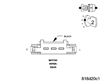
Turn the ignition off.
Disconnect the Rear Wiper Motor harness connector.
Turn the ignition on.
With the scan tool, read the Rear Wiper Park Switch Sense.
Does the Rear Wiper Park Switch Sense display: True?
Yes
- Replace the Rear Wiper Motor in accordance with the Service Information.
- Perform the BODY VERIFICATION TEST — VER 1. (Refer to 8 - ELECTRICAL/ELECTRONIC CONTROL MODULES - STANDARD PROCEDURE)
No
- Go To 3
3. CHECK (W17) REAR WIPER PARK SWITCH SENSE CIRCUIT FOR A SHORT TO GROUND
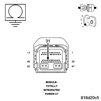
Turn the ignition off.
Disconnect the TIPM C7 harness connector.
Measure the resistance between ground and the (W17) Rear Wiper Park Switch Sense Circuit.
Is the resistance above 10k ohms?
Yes
- Replace the TIPM in accordance with the service information.
- Perform the BODY VERIFICATION TEST — VER 1.
No
- Repair the (W7) Wiper Park Switch Sense circuit for a short to ground.
- Perform the BODY VERIFICATION TEST — VER 1. (Refer to 8 - ELECTRICAL/ELECTRONIC CONTROL MODULES - STANDARD PROCEDURE)
B230E-REAR WIPER PARK SWITCH INPUT CIRCUIT HIGH (STUCK HIGH)
For a complete wiring diagram Refer to Section 8W.
- When Monitored:
With the ignition on.
- Set Condition:
The Totally Integrated Power Module (TIPM) does not detect a change from High to Low voltage on the Rear Wiper Park Switch Sense Circuit.
| Possible Causes |
| (W17) REAR WIPER PARK SWITCH SENSE CIRCUIT OPEN |
| (W17) REAR WIPER PARK SWITCH SENSE CIRCUIT SHORTED TO VOLTAGE |
| REAR WIPER MOTOR |
| TOTALLY INTEGRATED POWER MODULE |
Diagnostic Test
1. INTERMITTENT CONDITIONTurn the ignition on.
With the scan tool, clear all DTC's.
Cycle the Wiper Switch on and off 3 times.
With the scan tool, read DTC's.
Does the scan tool display this DTC as active?
Yes
- Go To 2
No
- The condition that caused this symptom is currently not present. Check for an intermittent condition by inspecting the related wiring harness for chafed, pierced, pinched, and partially broken wires. Also, inspect the related connectors for broken, bent, pushed out, spread, corroded, or contaminated terminals. Repair as necessary.
- Perform the BODY VERIFICATION TEST — VER 1. (Refer to 8 - ELECTRICAL/ELECTRONIC CONTROL MODULES - STANDARD PROCEDURE)
2. (W17) WIPER PARK SWITCH SENSE CIRCUIT SHORTED TO VOLTAGE
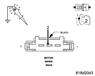
Turn the ignition off.
Disconnect the Rear Wiper Motor harness connector.
Turn the ignition on.
Using a 12–volt test light connected to ground, probe the (W17) Rear Wiper Park Switch Sense circuit.
Does the test light illuminate brightly?
Yes
- Repair the (W17) Rear Wiper Park Switch Sense circuit for a short to voltage.
- Perform the BODY VERIFICATION TEST — VER 1. (Refer to 8 - ELECTRICAL/ELECTRONIC CONTROL MODULES - STANDARD PROCEDURE)
No
- Go To 3
3. CHECK THE REAR WIPER MOTOR
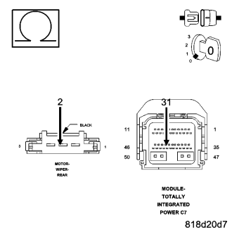
Connect a jumper wire between the (W17) Rear Wiper Park Switch Sense circuit and ground.
With the scan tool, read the Rear Wiper Park Switch Sense.
Does the Rear Wiper Park Switch Sense display: True?
Yes
- Replace the Rear Wiper Motor in accordance with the Service Information.
- Perform the BODY VERIFICATION TEST — VER 1. (Refer to 8 - ELECTRICAL/ELECTRONIC CONTROL MODULES - STANDARD PROCEDURE)
No
- Go To 4
4. (W17) REAR WIPER PARK SWITCH SENSE CIRCUIT OPEN
Turn the ignition off.
Disconnect the TIPM C7 harness connector.
Measure the resistance of the (W17) Rear Wiper Park Switch Sense circuit between the Rear Wiper Motor harness connector and the TIPM C7 harness connector.
Is the resistance below 10.0 ohms?
Yes
- Replace the Totally Integrated Power Module (TIPM) in accordance with the Service Information.
- Perform the BODY VERIFICATION TEST — VER 1. (Refer to 8 - ELECTRICAL/ELECTRONIC CONTROL MODULES - STANDARD PROCEDURE)
No
- Repair the (W17) Rear Wiper Park Switch Sense circuit for an open.
- Perform the BODY VERIFICATION TEST - VER 1. (Refer to 8 - ELECTRICAL/ELECTRONIC CONTROL MODULES - STANDARD PROCEDURE)
B2323-HEADLAMP WASHER MOTOR CONTROL CIRCUIT LOW
For a complete wiring diagram Refer to Section 8W.
- When Monitored:
With the Headlamp Washers activated.
- Set Condition:
When the Totally Integrated Power Module (TIPM) detects an shorted low condition.
| Possible Causes |
| (W28) HEADLAMP WASHER RELAY SUPPLY CIRCUIT OPEN |
| (W20) HEADLAMP WASHER RELAY CONTROL CIRCUIT SHORT TO GROUND |
| HEADLAMP WASHER RELAY |
| HEADLAMP WASHER MOTOR |
| TOTALLY INTEGRATED POWER MODULE |
Diagnostic Test
1. INTERMITTENT CONDITIONTurn the ignition on.
With the scan tool, clear all DTC's.
Turn the Headlamp Washers on.
With the scan tool read DTC's.
Does the scan tool display this DTC as active?
Yes
- Go To 2
No
- The condition that caused this symptom is currently not present. Check for an intermittent condition by inspecting the related wiring harness for chafed, pierced, pinched, and partially broken wires. Also, inspect the related connectors for broken, bent, pushed out, spread, corroded, or contaminated terminals. Repair as necessary.
- Perform the BODY VERIFICATION TEST-VER1. (Refer to 8 - ELECTRICAL/ELECTRONIC CONTROL MODULES - STANDARD PROCEDURE)
2. (W28) HEADLAMP WASHER RELAY SUPPLY CIRCUIT OPEN
NOTE: Check all fuses and circuit breakers before proceeding with the diagnosis of this DTC.
Turn the ignition off.
Remove the Headlamp Washer relay.
Turn the ignition on.
Measure the voltage on the (W28) Headlamp Washer Relay Supply circuit at the Headlamp Washer relay.
Is the voltage above 10.0 volts?
Yes
- Go To 3
No
- Repair the (W28) Headlamp Washer Relay Supply circuit for an open.
- Perform the BODY VERIFICATION TEST — VER 1. (Refer to 8 - ELECTRICAL/ELECTRONIC CONTROL MODULES - STANDARD PROCEDURE)
3. HEADLAMP WASHER RELAY
Turn the ignition off.
Replace the Headlamp Washer relay with a known good relay.
Turn the ignition on.
With the Scan Tool, clear all DTC's.
Activate the Headlamp Washers.
With the Scan Tool, read the DTC's.
Does the scan tool display this DTC as active?
Yes
- Go To 4
No
- Replace the Headlamp Washer relay in accordance with the Service Information.
- Perform the BODY VERIFICATION TEST — VER 1. (Refer to 8 - ELECTRICAL/ELECTRONIC CONTROL MODULES - STANDARD PROCEDURE)
4. (W20) HEADLAMP WASHER RELAY CONTROL CIRCUIT SHORT TO GROUND
Turn the ignition off.
Disconnect the TIPM C3 Connector.
Measure the resistance to ground of the (W20) Headlamp Washer Relay Control circuit.
Is the resistance below 5.0 ohms?
Yes
- Repair the (W20) Headlamp Washer Relay Control circuit for a short to ground.
- Perform the BODY VERIFICATION TEST — VER 1. (Refer to 8 - ELECTRICAL/ELECTRONIC CONTROL MODULES - STANDARD PROCEDURE)
No
- Replace the Totally Integrated Power Module (TIPM) in accordance with the Service Information.
- Perform the BODY VERIFICATION TEST — VER 1. (Refer to 8 - ELECTRICAL/ELECTRONIC CONTROL MODULES - STANDARD PROCEDURE)
B2324-HEADLAMP WASHER MOTOR CONTROL CIRCUIT HIGH
For a complete wiring diagram Refer to Section 8W.
- When Monitored:
With the Headlamp Washers activated.
- Set Condition:
When the Totally Integrated Power Module (TIPM) detects an HIGH condition.
| Possible Causes |
| (W24) HEADLAMP WASHER RELAY CONTROL CIRCUIT OPEN |
| (W24) HEADLAMP WASHER RELAY CONTROL CIRCUIT SHORTED TO VOLTAGE |
| (W23) HEADLAMP WASHER MOTOR CONTROL CIRCUIT OPEN |
| (W23) HEADLAMP WASHER MOTOR CONTROL CIRCUIT SHORTED TO VOLTAGE |
| HEADLAMP WASHER RELAY |
| TOTALLY INTEGRATED POWER MODULE |
Diagnostic Test
1. INTERMITTENT CONDITIONTurn the ignition on.
With the scan tool, clear all DTC's.
Turn the Headlamp Washers on.
With the scan tool, read DTC's.
Does the scan tool display active: B2324–HEADLAMP WASHER MOTOR CONTROL CIRCUIT HIGH?
Yes
- Go To 2
No
- The condition that caused this symptom is currently not present. Check for an intermittent condition by inspecting the related wiring harness for chafed, pierced, pinched, and partially broken wires. Also, inspect the related connectors for broken, bent, pushed out, spread, corroded, or contaminated terminals. Repair as necessary.
- Perform the BODY VERIFICATION TEST - VER 1. (Refer to 8 - ELECTRICAL/ELECTRONIC CONTROL MODULES - STANDARD PROCEDURE)
2. CHECK HEADLAMP WASHER RELAY
Turn the ignition off.
Remove the Headlamp Washer relay.
Turn the ignition on.
Turn the Headlamp Washers on.
With the scan tool, read DTC's.
Does the scan tool display active: B2324–HEADLAMP WASHER MOTOR CONTROL CIRCUIT HIGH?
Yes
- Go To 3
No
- Go To 5
3. (W24) HEADLAMP WASHER RELAY CONTROL CIRCUIT OPEN
Turn the ignition off.
Disconnect the TIPM C3 harness connector.
Measure the resistance of the (W24) Headlamp Washer Relay Control circuit between the Headlamp Washer Relay connector and the TIPM C3 harness connector.
Is the resistance below 10.0 ohms?
Yes
- Go To 4
No
- Repair the (W24) Headlamp Washer Relay Control circuit for an open.
- Perform the BODY VERIFICATION TEST - VER 1. (Refer to 8 - ELECTRICAL/ELECTRONIC CONTROL MODULES - STANDARD PROCEDURE)
4. (W24) HEADLAMP WASHER RELAY CONTROL CIRCUIT SHORTED TO VOLTAGE
Turn the ignition on.
Measure for voltage on the (W24) Headlamp Washer Relay Control circuit.
Is the voltage above 10.0 volts?
Yes
- Repair the (W24) Headlamp Washer Relay Control circuit for a short to voltage.
- Perform the BODY VERIFICATION TEST - VER 1. (Refer to 8 - ELECTRICAL/ELECTRONIC CONTROL MODULES - STANDARD PROCEDURE)
No
- Replace the Totally Integrated Power Module (TIPM) in accordance with the Service Information.
- Perform the BODY VERIFICATION TEST - VER 1. (Refer to 8 - ELECTRICAL/ELECTRONIC CONTROL MODULES - STANDARD PROCEDURE)
5. HEADLAMP WASHER RELAY
Turn the ignition off.
Replace the Headlamp Washer relay with a known good relay.
Turn the ignition on.
Turn the Headlamp Washers on.
With the scan tool, read DTC's.
Does the scan tool display active: B2324–HEADLAMP WASHER MOTOR CONTROL CIRCUIT HIGH?
Yes
- Go To 6
No
- Test Complete.
- Perform the BODY VERIFICATION TEST - VER 1. (Refer to 8 - ELECTRICAL/ELECTRONIC CONTROL MODULES - STANDARD PROCEDURE)
6. (W23) HEADLAMP WASHER MOTOR CONTROL CIRCUIT OPEN
Turn the ignition off.
Remove the Headlamp Washer relay.
Disconnect the Headlamp Washer Motor harness connector.
Measure the resistance of the (W23) Headlamp Washer Motor Control circuit at the Headlamp Washer Motor harness connector and the Headlamp Washer Relay connector.
Is the resistance below 10.0 ohms?
Yes
- Go To 7
No
- Repair the (W23) Headlamp Washer Motor Control circuit for an open.
- Perform the BODY VERIFICATION TEST - VER 1. (Refer to 8 - ELECTRICAL/ELECTRONIC CONTROL MODULES - STANDARD PROCEDURE)
7. (W23) HEADLAMP WASHER MOTOR CONTROL CIRCUIT SHORTED TO VOLTAGE
Turn the ignition on.
Measure for voltage on the (W23) Headlamp Washer Motor Control circuit.
Is the voltage above 10.0 volts?
Yes
- Repair the (W23) Headlamp Washer Motor Control circuit for a short to voltage.
- Perform the BODY VERIFICATION TEST - VER 1. (Refer to 8 - ELECTRICAL/ELECTRONIC CONTROL MODULES - STANDARD PROCEDURE)
No
- Replace the Headlamp Washer Motor in accordance with the Service Information.
- Perform the BODY VERIFICATION TEST - VER 1. (Refer to 8 - ELECTRICAL/ELECTRONIC CONTROL MODULES - STANDARD PROCEDURE)
B2376-REAR WIPER SWITCH INPUT CIRCUIT
For a complete wiring diagram Refer to Section 8W.
- When Monitored:
- With the ignition on.
- Set Condition:
- When the TIPM detects a short/low condition on the Rear Wiper Motor Control circuit.
| Possible Causes |
| (W13) REAR WIPER MOTOR CONTROL CIRCUIT SHORTED |
| REAR WIPER MOTOR |
| TOTALLY INTEGRATED POWER MODULE |
Diagnostic Test
1. INTERMITTENT CONDITIONTurn the ignition on.
With the Scan Tool, clear all TIPM DTC's.
Turn the Washers on.
With the Scan Tool, read the Wiper/Washers DTC's.
Does the Scan Tool read: B2376-REAR WIPER SWITCH INPUT CIRCUIT?
Yes
- Go To 2
No
- The condition that caused the symptom is currently not present. Inspect the related wiring for a possible intermittent condition. Look for any chafed, pierced, pinched, or partially broken wires.
- Perform the BODY VERIFICATION TEST — VER 1. (Refer to 8 - ELECTRICAL/ELECTRONIC CONTROL MODULES - STANDARD PROCEDURE)
2. REAR WIPER MOTOR
Turn the ignition off.
Disconnect the Rear Wiper Motor connector.
Turn the ignition on.
With the Scan Tool, read the DTC's.
Does the Scan Tool read: B2376-REAR WIPER SWITCH INPUT CIRCUIT?
Yes
- Go To 3
No
- Replace the Rear Wiper Motor in accordance with the service information.
- Perform the BODY VERIFICATION TEST — VER 1. (Refer to 8 - ELECTRICAL/ELECTRONIC CONTROL MODULES - STANDARD PROCEDURE)
3. (W13) REAR WIPER MOTOR CONTROL CIRCUIT SHORTED
Turn the ignition off.
Disconnect the Rear Wiper Motor harness connector.
Disconnect the TIPM C6 harness connector.
Measure the resistance between the (W13) RearWiper Motor Control Circuit and ground in the TIPM.
Is the resistance below 5.0 ohms?
Yes
- Repair the (W13) Rear Wiper Motor Control Circuit for a shorted condition.
- Perform the BODY VERIFICATION TEST — VER 1. (Refer to 8 - ELECTRICAL/ELECTRONIC CONTROL MODULES - STANDARD PROCEDURE)
No
- Replace the Totally Integrated Power Module in accordance with the service information.
- Perform the BODY VERIFICATION TEST — VER 1.