WASHER RESERVOIR
DESCRIPTION
Two unique washer reservoirs are used in this vehicle: one is used for gasoline engine applications, while the other is used for diesel engine applications.
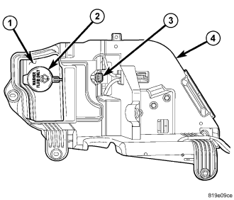
The gasoline engine washer fluid reservoir (1) is integral to the molded plastic component tray (4) located in the left front corner of the engine compartment. The same reservoir is used for vehicles regardless of whether they have only the front washer system or both the front and rear washer systems. Vehicles with both front and rear washer systems have a bi-directional washer pump/motor unit (3) installed in the reservoir in place of a single direction pump. The upper portion of the reservoir is constructed of a translucent plastic, while the lower portion of the reservoir is constructed of the same opaque plastic as the remainder of the component tray. A bright yellow plastic filler cap (2) with an International Control and Display Symbol icon for Windshield Washer molded into it snaps over the open end of the filler neck. The cap hinges on and is secured to a molded-in hook formation on the top of the reservoir behind the filler neck.
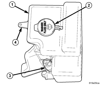
The diesel engine washer fluid reservoir (1) is also located in the left front corner of the engine compartment, but is secured to the left side of the radiator fan shroud. As with the gasoline engine version, the same reservoir is used for vehicles regardless of whether they have only the front washer system or both the front and rear washer systems. Vehicles with both front and rear washer systems have a bi-directional washer pump/motor unit (3) installed in the reservoir in place of a single direction pump. This reservoir is molded entirely of translucent plastic and is secured to the fan shroud through an integral mounting tab at the top (4) with a screw and a U-nut to the top of the shroud, an integral T-tab on the front of the reservoir that engages a slot in the shroud, and two integral tabs at the bottom that engage two slots in the shroud. This reservoir also has a bright yellow plastic filler cap (2) with an International Control and Display Symbol icon for Windshield Washer molded into it snaps over the open end of the filler neck. The cap hinges on and is secured to a molded-in hook formation on the top of the reservoir behind the filler neck.
There is a dedicated hole in the sump area of each reservoir provided for the washer pump/motor unit. The component tray has a well just behind the reservoir that allows service access to the washer pump, while the diesel engine pump is accessed on the lower left side of the reservoir. Both reservoirs include an integral receptacle to accept the snap post on the top of the washer pump/motor units. The component tray has integral clips on its lower surface for routing the washer hoses, while the diesel washer hoses are retained by plastic routing clips to the engine compartment wire harness on the left side of the engine compartment.
Washer reservoirs cannot be repaired and, if ineffective or damaged, they must be replaced. The gasoline engine reservoir is service only as a unit with the left component tray. The diesel engine washer reservoir, the rubber grommet seal/filter screens for the washer pump/motor units and the filler caps are each available for individual service replacement.
OPERATION
The washer fluid reservoir provides a secure, on-vehicle storage location for a large reserve of washer fluid for operation of the front and rear washer systems. The washer reservoir filler cap provides a clearly marked and readily accessible point from which to add washer fluid to the reservoir. The washer pump/motor unit is located in a sump area near the base of the reservoir to be certain that washer fluid will be available to the pump as the fluid level in the reservoir becomes depleted. The washer pump/motor unit is mounted in the lowest position in the sump.
REMOVAL
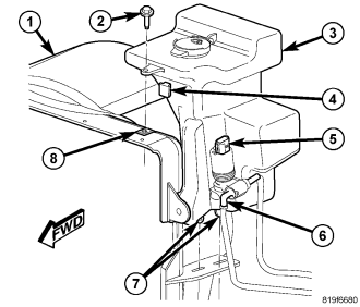
NOTE: The following procedure applies only to the washer reservoir used with an optional diesel engine. The washer reservoir for vehicles with a gasoline engine is integral to the molded plastic component tray on the left side of the engine compartment.
1. Disconnect and isolate the negative battery cable.
2. Siphon the washer fluid from the washer reservoir (3) into a clean container for reuse.
3. Disconnect the engine compartment wire harness connector from the washer pump/motor (5).
NOTE: To aid in reinstallation, note the installed position of the washer hoses prior to disconnecting them.
4. Disconnect the front and rear washer hoses (6) from the washer pump on the outboard side of the reservoir.
5. Remove the screw (2) that secures the mounting tab on the top of the reservoir to the U-nut (8) in the top of the radiator fan shroud (1).
6. Pull the washer reservoir upward far enough to disengage the integral T-tab (4) on the front of the reservoir and the two integral tabs (7) on the bottom of the reservoir from their respective slots in the shroud.
7. Remove the washer reservoir from the engine compartment.
INSTALLATION
NOTE: The following procedure applies only to the washer reservoir used with an optional diesel engine. The washer reservoir for vehicles with a gasoline engine is integral to the molded plastic component tray on the left side of the engine compartment.
1. Check to be certain that the U-nut (8) is in good condition and properly installed in the top of the radiator fan shroud (1).
2. Position the washer reservoir (3) into the left front corner of the engine compartment.
3. Align and engage the integral T-tab (4) on the front of the reservoir and the two integral tabs (7) on the bottom of the reservoir with their respective slots in the shroud.
4. Install and tighten the screw (2) that secures the integral mounting tab on the top of the reservoir to the U-nut on the top of the shroud. Tighten the screw to 9 N·m (79 in. lbs.).
NOTE: Be certain to reconnect the front and rear washer hoses to the proper outlet nipples from the washer pump. Failure to properly connect the hoses will cause the front and rear washer systems to operate incorrectly.
5. Reconnect the front and rear washer hoses (6) to the washer pump on the outboard side of the reservoir.
6. Reconnect the engine compartment wire harness connector to the washer pump/motor unit (5).
7. Refill the washer reservoir with the washer fluid drained during removal.
8. Reconnect the battery negative cable.