WIPER MOTOR
DESCRIPTION
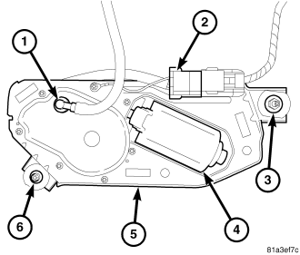
The rear wiper motor is concealed behind a molded plastic trim cover on the inside of the lift glass near the left liftglass hinge at the top of the glass. A large blackout area of the lift glass conceals the unit from the exterior of the vehicle. The end of the motor output shaft that protrudes through and is sealed to a clearance hole in the lift glass to drive the rear wiper arm and blade is the only visible component of the rear wiper motor. Rubber inner and outer seals, plastic inner and outer spacers and a large nut secure and seal the motor output shaft housing to the lift glass. A motor pigtail harness connector (2) is secured to the outboard upper corner of the motor bracket, and connects the rear wiper motor to the vehicle electrical system through a dedicated take out and connector of the hard top wire harness. The rear wiper motor consists of the following major components:
- Bracket (5) - The rear wiper motor bracket consists of a stamped steel mounting plate that is secured with screws to the wiper motor and transmission. A rubber insulator in a tab on the upper outboard corner of the bracket is secured by a nut and washer (3) to a stud that also secures the lower end of the left lift glass hinge to the glass. Another tab with a rubber insulator and a threaded metal insert on the inboard lower corner of the bracket is secured by a special threaded fastener (6) to the outside surface of the lift glass.
- Motor (4) - The single-speed permanent magnet rear wiper motor is secured with screws to the rear wiper motor bracket. The wiper motor includes an integral transmission, a motor output shaft, an automatic resetting circuit breaker and the rear wiper motor park switch. Washer fluid is fed through a nipple (1) on the transmission housing through the output shaft to the rear washer nozzle on the end of the output shaft.
The rear wiper motor cannot be adjusted or repaired. If any component of the motor is faulty or damaged, the entire rear wiper motor unit must be replaced. The motor output shaft housing rubber seals, spacers, nut and nut cover are available for individual service replacement.
OPERATION
The rear wiper motor operation is controlled by the Totally Integrated Power Module (TIPM), which uses intelligent, high current, self-protected high side switches to control rear wiper system operation for energizing or de-energizing the rear wiper motor. The TIPM uses internal programming and electronic messages received over the Controller Area Network (CAN) data bus from the ElectroMechanical Instrument Cluster (EMIC) (also known as the Cab Compartment Node/CCN) to provide the appropriate rear wiper and washer system operating modes. The EMIC uses electronic messages received from the Steering Control Module (SCM) over a Local Interconnect Network (LIN) data bus to determine when to send electronic rear wiper system requests to the TIPM.
The rear wiper motor park switch is a single pole, single throw, momentary switch within the wiper motor that is mechanically actuated by the wiper motor transmission components. The park switch alternately closes and opens a path to ground for the rear wiper motor electronic control logic circuitry of the TIPM, depending upon the position of the rear wiper blade on the liftgate glass. This input allows the electronic logic circuits of the TIPM to control all of the electronic features of rear wiper motor operation and to keep the motor energized long enough to complete its current wipe cycle and park the wiper blade after the wiper system or the ignition switch has been turned OFF.
The rear wiper motor is grounded at all times through a take out in the body wire harness that is secured to a ground location in the passenger compartment. The automatic resetting circuit breaker protects the motor from overloads. The rear wiper motor transmission converts the rotary output of the wiper motor to the back and forth wiping motion of the rear wiper arm and blade on the liftgate glass.
The hard wired inputs and outputs of the rear wiper motor may be diagnosed using conventional diagnostic tools and procedures. Refer to the appropriate wiring information. However, conventional diagnostic methods will not prove conclusive in the diagnosis of the rear wiper motor or the electronic controls or communication between other modules and devices that provide some features of the rear wiper and washer system. The most reliable, efficient, and accurate means to diagnose the rear wiper motor or the electronic controls and communication related to rear wiper motor operation requires the use of a diagnostic scan tool. Refer to the appropriate diagnostic information.
REMOVAL
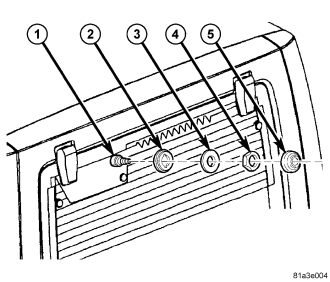
1. Disconnect and isolate the battery negative cable.
2. Remove the rear wiper arm from the rear wiper motor output shaft (1). (Refer to 8 - ELECTRICAL/WIPERS/WASHERS/WIPER ARM - REMOVAL - REAR).
3. Remove the plastic nut cover (5) from the output shaft.
4. Remove the nut (4) that secures the output shaft to the lift glass.
5. Remove the plastic spacer (3) and the rubber seal (2) from the output shaft.
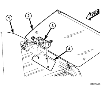
6. Open the swing gate and raise the lift glass (2).
7. Grasp the edges of the rear wiper motor cover (4) and pull it firmly downward to disengage the three snap clip retainers that secure it to the rear wiper motor bracket (3).
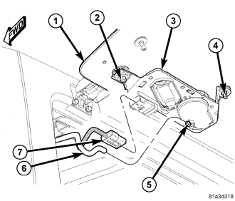
8. Disconnect the hardtop washer hose (6) from the rear washer nozzle nipple (5) on the rear wiper motor (3) transmission housing.
9. Disconnect the hardtop wire harness connector (7) from the rear wiper motor pigtail wire harness connector.
NOTE: The special fastener does not have a left-hand thread, but because it is being driven from the threaded end of the fastener rather than from the head, it must be rotated clockwise to loosen and counterclockwise to tighten.
10. While supporting the rear wiper motor with one hand, remove the special fastener (4) that secures the motor mounting bracket to the outside of the lift glass (1).
11. While still supporting the rear wiper motor, remove the nut (2) that secures the motor mounting bracket to the left lift glass hinge lower stud.
12. Remove the motor and bracket unit from the inside of the lift glass.
INSTALLATION
1. Position the rear wiper motor and bracket unit (3) to the inside of the lift glass (1). Be certain that the plastic inner spacer and rubber seal on the output shaft housing are in place between the output shaft housing and the clearance hole in the lift glass.
2. While supporting the rear wiper motor with one hand, install and tighten the nut (2) that secures the motor mounting bracket to the left lift glass hinge lower stud. Tighten the nut to 6 N·m (53 in. lbs.).
NOTE: The special fastener does not have a left-hand thread, but because it is being driven from the threaded end of the fastener rather than from the head, it must be rotated clockwise to loosen and counterclockwise to tighten.
3. While still supporting the wiper motor with one hand, install and tighten the special fastener (4) that secures the motor mounting bracket to the outside of the lift glass. Tighten the special fastener to 4 N·m (35 in. lbs.).
4. Reconnect the hardtop wire harness connector (7) to the rear wiper motor pigtail wire harness connector.
5. Reconnect the hardtop washer hose (6) to the rear washer nozzle nipple (5) on the rear wiper motor transmission housing.
6. Insert the guide pins on the rear surface of the rear wiper motor cover (4) into the round clearance holes in the rear wiper motor bracket (3).
7. Using hand pressure, press the cover against wiper motor bracket until the three snap clip retainers that secure it snap into place.
8. Lower the lift glass (2) and close the swing gate.
9. Install the rubber seal (2) and the plastic spacer (3) over the rear wiper motor output shaft (1).
10. Install and tighten the nut (4) that secures the output shaft to the lift glass. Tighten the nut to 4 N·m (35 in. lbs.).
11. Install the plastic nut cover (5) over the output shaft.
12. Reinstall the rear wiper arm onto the output shaft. (Refer to 8 - ELECTRICAL/WIPERS/WASHERS/WIPER ARM - INSTALLATION - REAR).
13. Reconnect the battery negative cable.