DESCRIPTION
- DESCRIPTION - HOW TO USE WIRING DIAGRAMS
- DESCRIPTION - CIRCUIT INFORMATION
- DESCRIPTION - CIRCUIT FUNCTIONS
- DESCRIPTION - SECTION IDENTIFICATION AND INFORMATION
- DESCRIPTION - CONNECTOR, GROUND AND SPLICE INFORMATION
DESCRIPTION - HOW TO USE WIRING DIAGRAMS
DaimlerChrysler Corporation wiring diagrams are designed to provide information regarding the vehicles wiring content. In order to effectively use the wiring diagrams to diagnose and repair DaimlerChrysler Corporation vehicles, it is important to understand all of their features and characteristics.
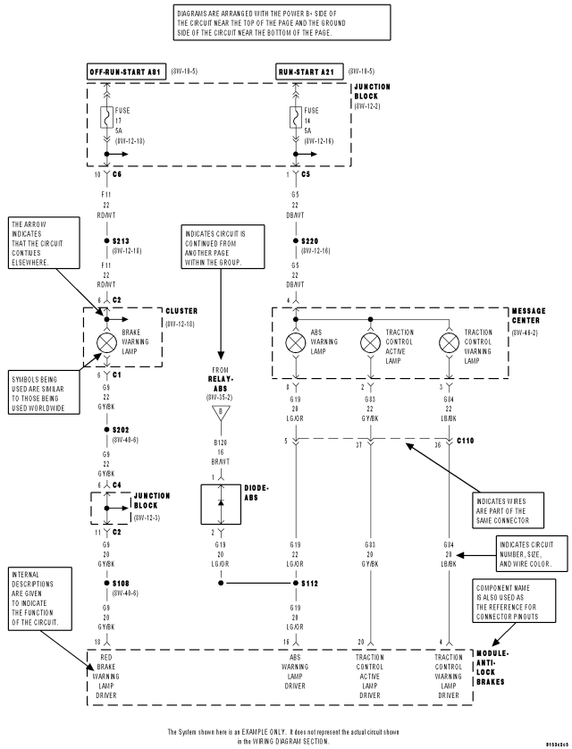
Diagrams are arranged such that the power (B+) side of the circuit is placed near the top of the page, and the ground (B-) side of the circuit is placed near the bottom of the page.
All switches, components, and modules are shown in the at rest position with the doors closed and the key removed from the ignition.
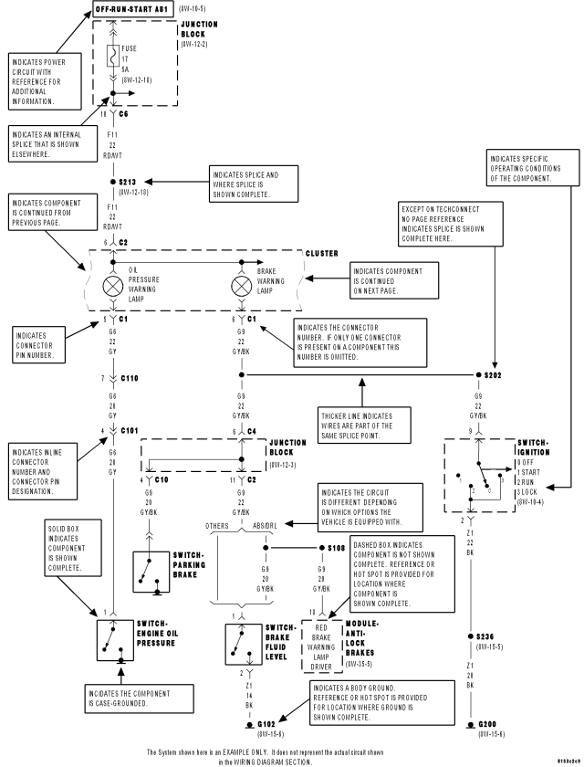
Components are shown two ways. A solid line around a component indicates that the component is complete. A dashed line around the component indicates that the component is being shown is not complete. Incomplete components have a reference number to indicate the page where the component is shown complete.
It is important to realize that no attempt is made on the diagrams to represent components and wiring as they appear on the vehicle. For example, a short piece of wire is treated the same as a long one. In addition, switches and other components are shown as simply as possible, with regard to function only.
SYMBOLS
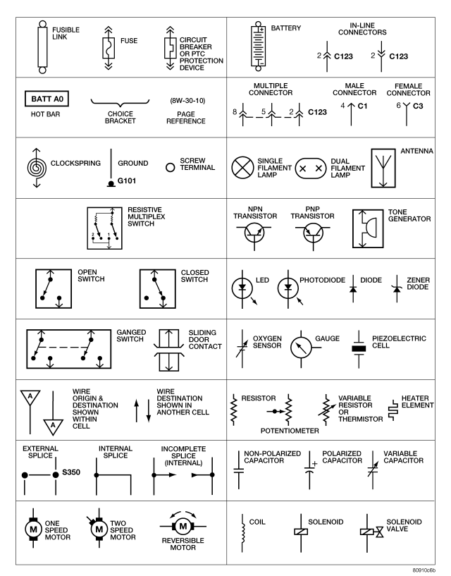
International symbols are used throughout the wiring diagrams. These symbols are consistent with those being used around the world.
TERMINOLOGY
This is a list of terms and definitions used in the wiring diagrams.
DESCRIPTION - CIRCUIT INFORMATION
Each wire shown in the diagrams contains a code which identifies the main circuit, a specific part of the main circuit, gage of wire, and color. An example would be A 2 18 LB/YL. This is a Battery Feed circuit, level two, eighteen gauge, light blue with a yellow tracer.
| COLOR CODE |
COLOR |
| BL |
BLUE |
| BK |
BLACK |
| BR |
BROWN |
| DB |
DARK BLUE |
| DG |
DARK GREEN |
| GY |
GRAY |
| LB |
LIGHT BLUE |
| LG |
LIGHT GREEN |
| OR |
ORANGE |
| PK |
PINK |
| RD |
RED |
| TN |
TAN |
| VT |
VIOLET |
| WT |
WHITE |
| YL |
YELLOW |
| * |
WITH TRACER |
DESCRIPTION - CIRCUIT FUNCTIONS
All circuits in the diagrams use an alpha/numeric code to identify the wire and it's function. To identify which circuit code applies to a system, refer to the Circuit Identification Code Chart. This chart shows the main circuits only and does not show the secondary codes that may apply to some models.
| CIRCUIT |
FUNCTION |
| A |
BATTERY FEED |
| B |
BRAKE CONTROLS |
| C |
CLIMATE CONTROLS |
| D |
DIAGNOSTIC
CIRCUITS |
| E |
DIMMING ILLUMINATION CIRCUITS |
| F |
FUSED CIRCUITS |
| G |
MONITORING CIRCUITS (GAUGES) |
| H |
MULTIPLE |
| I |
NOT USED |
| J |
OPEN |
| K |
POWERTRAIN CONTROL MODULE |
| L |
EXTERIOR LIGHTING |
| M |
INTERIOR
LIGHTING |
| N |
MULTIPLE |
| O |
NOT USED |
| P |
POWER OPTION (BATTERY
FEED) |
| Q |
POWER OPTIONS (IGNITION FEED) |
| R |
PASSIVE RESTRAINT |
| S |
SUSPENSION/STEERING |
| T |
TRANSMISSION/TRANSAXLE/ TRANSFER CASE |
| U |
OPEN |
| V |
SPEED
CONTROL, WIPER/WASHER |
| W |
WIPERS |
| X |
AUDIO SYSTEMS |
| Y |
TEMPORARY |
| Z |
GROUNDS |
DESCRIPTION - SECTION IDENTIFICATION AND INFORMATION
The wiring diagrams are grouped into individual sections. If a component is most likely found in a particular group, it will be shown complete (all wires, connectors, and pins) within that group. For example, the Auto Shutdown Relay is most likely to be found in Group 30, so it is shown there complete. It can, however, be shown partially in another group if it contains some associated wiring.
Splice diagrams in Section 8W-70 show the entire splice and provide references to other sections the splices serves. Section 8W-70 only contains splice diagrams that are not shown in their entirety somewhere else in the wiring diagrams.
Section 8W-80 shows each connector and the circuits involved with that connector. The connectors are identified using the name/number on the diagram pages.
DESCRIPTION - CONNECTOR, GROUND AND SPLICE INFORMATION
CAUTION: Not all connectors are serviced. Some connectors are serviced only with a harness. A typical example might be the Supplemental Restraint System connectors. Always check parts availability before attempting a repair.
IDENTIFICATION
In-line connectors are identified by a number, as follows:
- In-line connectors located in the engine compartment are C100 series numbers.
- In-line connectors located in the instrument panel area are C200 series numbers.
- In-line connectors located in the body are C300 series numbers.
- Jumper harness connectors are C400 series numbers.
- Grounds and ground connectors are identified with a “G” and follow the same series numbering as the in-line connectors.
- Splices are identified with an “S” and follow the same series numbering as the in-line connectors. In addition, S001–S099 numbers are located in the engine compartment.
- Component connectors are identified by the component name instead of a number. Multiple connectors on a component use a C1, C2, etc. identifier.
LOCATIONS
Section 8W-91 contains connector/ground/splice location illustrations. The illustrations contain the connector name (or number)/ground number/splice number and component identification. Connector/ground/splice location charts in section 8W-91 reference the figure numbers of the illustrations.
The abbreviation T/O is used in the component location section to indicate a point in which the wiring harness branches out to a component. The abbreviation N/S means Not Shown in the illustrations