Audio And Electronics
RHR NAVIGATION RADIO KIT
RHR NAVIGATION RADIO KIT
wRANGLER
 |
|
CALL OUT |
DESCRIPTION |
QUANTITY |
|---|---|---|
|
1 |
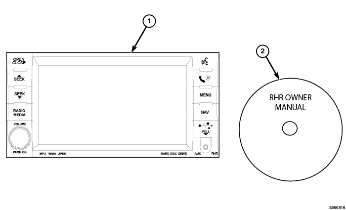
RHR Radio (AM/FM/CD/DVD/HDD/MP3/NAV) |
1 |
|
2 |
RHR Owner Manual DVD |
1 |
|
TOOLS REQUIRED |
|||
|---|---|---|---|
|
Phillips Head Screw Driver |
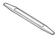
Fiber Trim Stick |
Scan Tool |
T25 Torx Screw Driver |
PROCEDURE STEPS:
 |
- Disconnect and isolate the negative battery cable.
- If equipped with power windows, using a fiber trim stick, gently pry the switch assembly (2) away from the trim panel (1), disconnect the electrical connector and remove the switch.
-
For vehicles without power windows, using a fiber trim stick, gently pry the storage bin assembly away from the bezel and remove the bin.
-
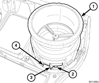
Each air outlet (1) is secured by a retaining tab (3) located on the outlet, and a stop tab (4) located on the back of the trim panel. Access the retaining tab from the inside of the air outlet, through the square openings (2) provided.
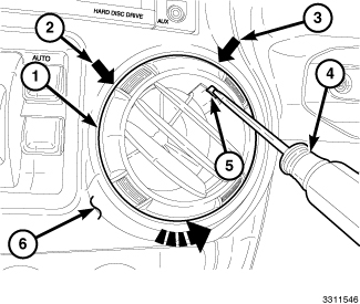
NOTE: Center-right outlet shown. Other outlet similar.
- Rotate the louvers of both air outlets (1) in the center of the instrument panel (6) to the eleven-o-clock position (2).
- Place a small screwdriver (4) or equivalent through the square opening (5) inside of each air outlet, located at the twelve-thirty position (3).
- Carefully pry the retaining tab (3, shown in previous illustration) toward the center of the air outlet and rotate the outlets counterclockwise.
-
Remove the air outlets from the trim panel.
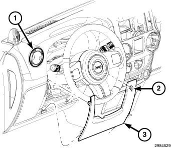
- Using a fiber trim stick, disengage the two retaining clips (1) that secure the top of the steering column opening cover (2) to the instrument panel.
-
Disengage the two lower retaining tabs and remove the steering column opening cover.
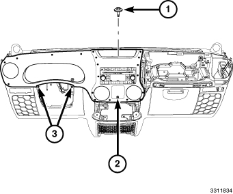
- Remove the storage bin mat and the screw (1), located at the top of the instrument panel.
- Remove the screw (2) through the center opening of the trim panel.
-
Remove the two screws (3) that secure the trim panel to the instrument panel, located at the steering column opening.
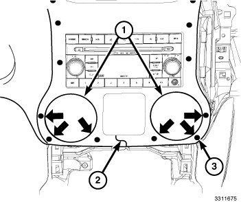
CAUTION: Do not use any tools to release the lower trim panel retaining clips. Failure to follow these instructions can result in damage to the trim panel and reinforcement.
-
Release the six lower retaining clips (3) without the use of tools. Reach into the instrument panel through the vent openings (1), firmly grasp the reinforcement located behind the trim panel (2) and carefully pull the reinforcement and trim panel assembly rearward.
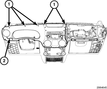
-
Release the remaining 13 retaining clips (1) and remove the trim panel (2).
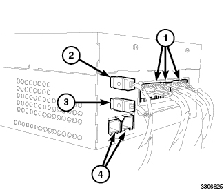
CAUTION: Pulling the antenna cable straight out of the radio without pulling on the locking antenna connector could damage the cable or radio.
- Remove the radio mounting screws.
- Pull the radio out far enough to access the back of the radio.
- Disconnect the AM/FM antenna (2) and electrical connectors (1).
- If equipped, disconnect the navigation antenna (3).
- If equipped, disconnect the USB connectors (4).
- Remove the radio from the instrument panel.
- Position the new radio to the instrument panel.
- Connect the AM/FM antenna (2) and electrical connectors (1).
- Connect the satellite/navigation antenna (3).
- If equipped, connect the USB connectors (4).
-
Install the radio mounting screws.
-
Position the trim panel (2) into place and fully seat all 19 retaining clips (1).
- Install the two screws (3) that secure the trim panel to the instrument panel, located at the steering column opening.
- Install the screw (2) through the center opening of the trim panel.
-
Install the screw and the storage bin mat at the center of the instrument panel.
- Position the steering column opening cover (2) to the instrument panel and engage the two lower retaining tabs.
-
Engage the two retaining clips (1) that secure the top of the steering column opening cover to the instrument panel.
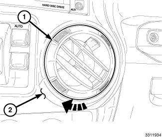
NOTE: Center-right outlet shown. Other outlet similar.
NOTE: If a foam seal on an air outlet is deformed or damaged, the seal must be replaced.
-
Install the air outlets (1) into the trim panel (2) and rotate the air outlets clockwise until fully engaged.
- If equipped with power windows, position the switch assembly (2) to the trim panel (1), connect the electrical connector and install the switch.
- For vehicles without power windows, install the storage bin assembly.
-
Reconnect the negative battery cable.
UPDATE VEHICLE CONFIGURATION
| NOTE: |
The wiTECH software level must be at the latest release to perform this procedure. |
- VIN must be updated with the sales code of the added accessory in order to enable system functionality. Using the DealerCONNECT website and the wiTECH diagnostic application, complete the vehicle configuration.
- Log on to https://dealerconnect.chrysler.com.
- In the "Vehicle Option" screen under the "Global Claims System" category in the "Service" tab, enter the vehicle VIN, four digit pin number obtained from the dealership parts department and add sales code(s) noted below as a "Dealer Installed Option". RHR (AM/FM/DVD/HDD with SDARS)
- Confirm that the new sales code has been successfully added to the VIN.
- With the wiTECH diagnostic application, perform the following steps form the Initial Start Up Screen:
RHR HANDS FREE ADAPTER WITH USB
RHR HANDS FREE ADAPTER WITH USB
WRANGLER
 |
|
CALL OUT |
DESCRIPTION |
QUANTITY |
|---|---|---|
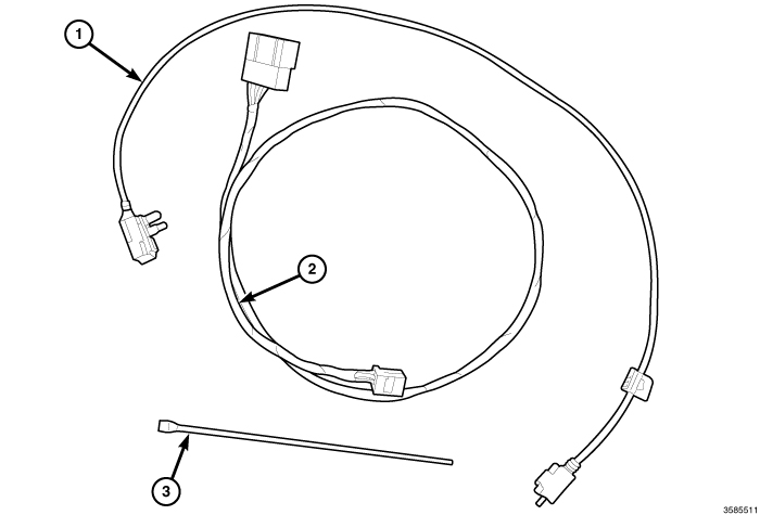
|
1 |
USB Extension Cable |
1 |
|
2 |
Hands Free Wiring Harness |
1 |
|
3 |
Tie strap |
8 |
|
TOOLS REQUIRED |
||||
|---|---|---|---|---|
|
Phillips Head Screw Driver |
7mm Socket and Wrench |
T20 Torx Screw Driver |
10mm Wrench |
 |
-
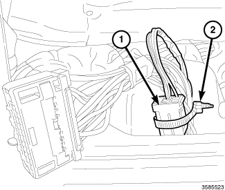
After removing the 10-way connector (1) from the back of the radio, secure it to the existing harness with a tie strap (2).
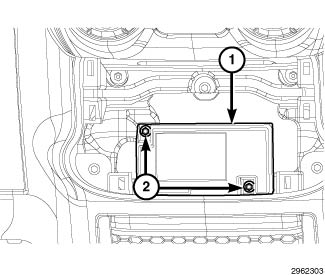
- Disconnect the electrical connector from the Hands Free Module (HFM) (1).
-
If equipped with a USB cable, disconnect the USB connector from the HFM.
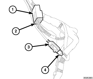
- Connect the factory wiring harness connector (2) to the HFM overlay harness connector (1).
- If equipped with USB, connect the factory USB connector (4) to the USB extension harness connector (3).
- Route the overlay harness and extension cable along the existing harness to the radio and secure with the provided tie straps.
-
The HFM is located below the radio so there will be excess wire for the extension harness and USB extension cable. Loop the excess wire and secure it to prevent any noise or chafing.
- Position the radio to the instrument panel.
- Connect the AM/FM antenna (2).
- Connect the factory electrical connector (1) and the connector from the supplied wiring harness that was routed from the HFM.
- Connect the satellite/navigation antenna (3).
- If equipped, connect the USB connectors (4), including the one that was routed from the HFM.
-
Install the radio mounting screws.
-
Position the trim panel (2) into place and fully seat all 19 retaining clips (1).
- Install the two screws (3) that secure the trim panel to the instrument panel, located at the steering column opening.
- Install the screw (2) through the center opening of the trim panel.
-
Install the screw and the storage bin mat at the center of the instrument panel.
- Position the steering column opening cover (2) to the instrument panel and engage the two lower retaining tabs.
-
Engage the two retaining clips (1) that secure the top of the steering column opening cover to the instrument panel.
NOTE: Center-right outlet shown. Other outlet similar.
NOTE: If a foam seal on an air outlet is deformed or damaged, the seal must be replaced.
-
Install the air outlets (1) into the trim panel (2) and rotate the air outlets clockwise until fully engaged.
- If equipped with power windows, position the switch assembly (2) to the trim panel (1), connect the electrical connector and install the switch.
- For vehicles without power windows, install the storage bin assembly.
-
Reconnect the negative battery cable.
PROCEDURE STEPS:
|
- Disconnect and isolate the negative battery cable.
- If equipped with power windows, using Trim Stick C-4755 gently pry the switch assembly (2) away from the trim panel (1), disconnect the electrical connector and remove the switch.
-
For vehicles without power windows, using
Trim Stick C-4755 gently pry the storage bin assembly away from the bezel and remove the bin.
-
Each air outlet (1) is secured by a retaining tab (3) located on the outlet, and a stop tab (4) located on the back of the trim panel. Access the retaining tab from the inside of the air outlet, through the square openings (2) provided.
NOTE: Center-right outlet shown. Other outlet similar.
- Rotate the louvers of both air outlets (1) in the center of the instrument panel (6) to the eleven-o-clock position (2).
- Place a small screwdriver (4) or equivalent through the square opening (5) inside of each air outlet, located at the twelve-thirty position (3).
- Carefully pry the retaining tab (3, shown in previous illustration) toward the center of the air outlet and rotate the outlets counterclockwise.
-
Remove the air outlets from the trim panel.
- Using Trim Stick C-4755 disengage the two retaining clips (1) that secure the top of the steering column opening cover (2) to the instrument panel.
-
Disengage the two lower retaining tabs and remove the steering column opening cover.
- Remove the storage bin mat and the screw (1), located at the top of the instrument panel.
- Remove the screw (2) through the center opening of the trim panel.
-
Remove the two screws (3) that secure the trim panel to the instrument panel, located at the steering column opening.
CAUTION: Do not use any tools to release the lower trim panel retaining clips. Failure to follow these instructions can result in damage to the trim panel and reinforcement.
-
Release the six lower retaining clips (3) without the use of tools. Reach into the instrument panel through the vent openings (1), firmly grasp the reinforcement located behind the trim panel (2) and carefully pull the reinforcement and trim panel assembly rearward.
-
Release the remaining 13 retaining clips (1) and remove the trim panel (2).
CAUTION: Pulling the antenna cable straight out of the radio without pulling on the locking antenna connector could damage the cable or radio.
- Remove the radio mounting screws.
- Pull the radio out far enough to access the back of the radio.
- Disconnect the AM/FM antenna (2) and electrical connectors (1).
- If equipped, disconnect the navigation antenna (3).
- If equipped, disconnect the USB connectors (4).
-
Remove the radio from the instrument panel.
WI-FI ROUTER
WI-FI ROUTER
JEEP WRANGLER
PROCEDURE STEPS:
| NOTE: |
Using a test light, verify the cigarette lighter outlet being used is ignition switched. Power must not be present with the ignition in the OFF position. |
 |
- Disconnect the negative battery cable.
-
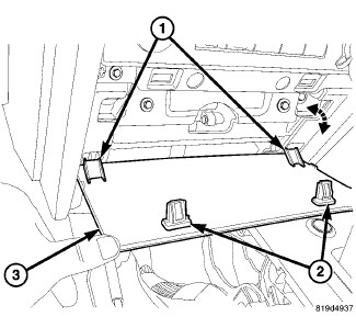
Using trim stick C-4755 or equivalent, release the clips (2) and rotate the lower center trim (3) down and release the tabs (1).
-
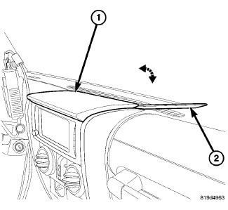
Using trim stick C-4755 or equivalent (2), release the clips in the rear of the upper trim (1).
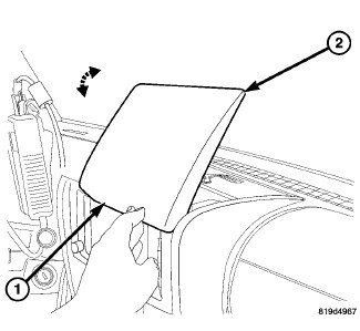
-
Rotate the upper trim (2) back and release the front (1).
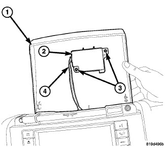
-
Disconnect the electrical connector (4) and remove the upper center cover (1).
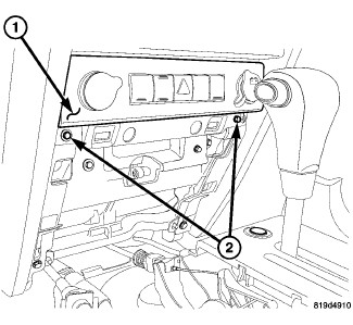
-
Remove the screws (2) and using trim stick C-4755 or equivalent, separate the center bezel (1).
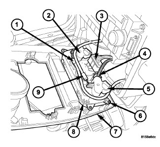
-
Disconnect the HVAC control cables (1 and 9) and disconnect the electrical connectors (3).
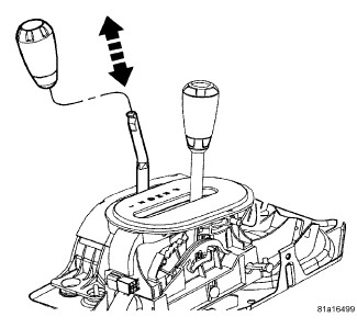
-
On 4x4 vehicles grasp the transfer case shifter knob and pull straight up and remove the knob.
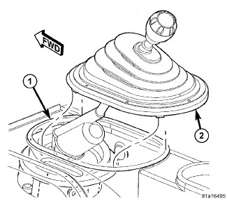
-
On manual transmission vehicles, using a trim stick C-4755 or equivalent, separate the shifter boot (2) from the console bezel (1).
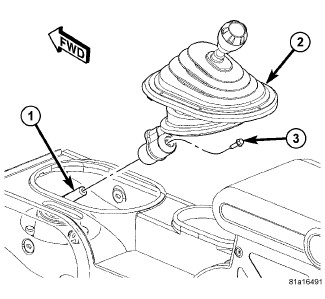
-
Remove the bolt (3) and remove the manual transmission shifter (2) from the shifter shaft (1).
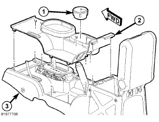
- Remove the cup holder or ash receiver (1), if equipped.
-
Using trim stick C-4755 or equivalent, remove the console bezel (2).
-
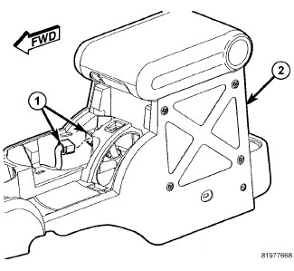
Disconnect the electrical connector (1).
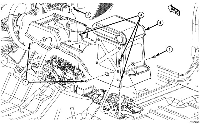
- Remove the four console screws (1).
- Lift the console (4) up off the clip retainers (3) and remove.
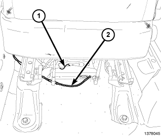
- Install the Wi-Fi router (1) under the passenger seat and secure it using the supplied Velcro® tape.
-
Route and secure the Wi-Fi power harness (2) under the center console to the cigarette lighter outlet wire harness.
NOTE: Do not use the power outlet for the power supply to the Wi-Fi router.
- Locate the cigarette lighter outlet wiring harness.
- Cut each wire and remove 13 mm (0.5 in.) of insulation from each wire that needs to be soldered/spliced.
-
Place a piece of supplied adhesive lined heat shrink tubing on one side of each cut wire. Insure the tubing will be long enough to cover and seal the entire soldered area.
CAUTION: Do not use acid core solder.
-
Solder the supplied fused pigtail to Wi-Fi power harness power wire.
-
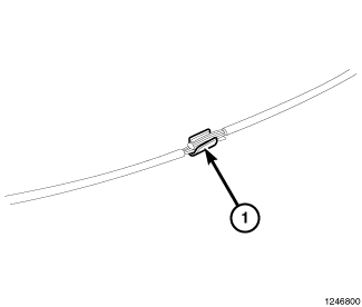
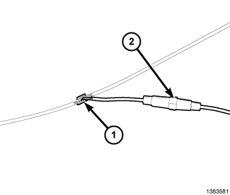
Place the strands of the power side wires overlapping each other inside of the splice clip (1).
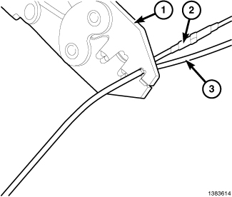
- Using crimping tool (1), Mopar® p/n 05019912AA or equivalent, crimp the splice clip and wires together.
-
Repeat the previous two steps for the ground side wires.
-
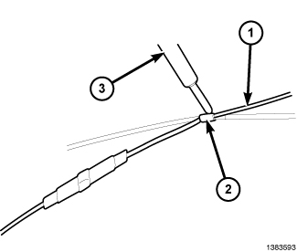
Solder (3) the connection (2) together using rosin core solder (1).
-
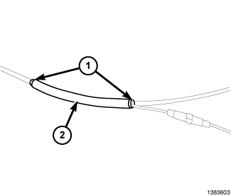
Center the heat shrink tubing (2) over the solder joint and heat using a heat gun. Heat the joint until the tubing is tightly sealed and sealant (1) comes out of both ends of the tubing.
- Position the console (4) over the shiftier and brake levers and seat the clips (3) fully.
- Install the four screws (1).
-
Connect the electrical connector (1).
- Position the bezel (2) over the shiftier and brake lever and seat the clips fully.
-
Install the cup holder and ash receiver (1), if equipped.
-
If equipped, position the transfer case shifter knob onto the shift shaft and seat fully.
- If equipped, position the manual transmission shifter handle (2) onto the shift shaft (1) and install the bolt (3).
-
Tighten the bolt (3) to 33 N·m (24.5 ft. lbs.)
-
Seat the shifter boot (2) onto the console bezel (1) and seat fully.
-
Connect the HVAC control cables (1 and 9) and connect the electrical connectors (3 and 4).
- Position the center bezel (1) onto the I/P and seat the clips fully.
-
Install the lower screws (2).
-
Connect the electrical connector (4) and position the upper center cover onto the top of the I/P.
-
Position the front of the cover (1) onto the center support and rotate the trim (2) back and seat the clips fully.
- Position the lower tabs (1) into the slots and rotate the trim (3) up and seat the clips (2) fully.
- Connect the negative battery cable.
-
Verify system operation.