Exterior Appearance
FRONT 1/2 DOOR KIT
FRONT 1/2 DOOR KIT
PROCEDURE STEPS:
JEEP WRANGLER
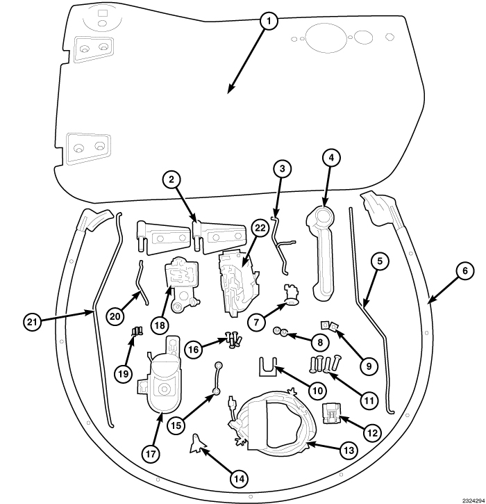
door SUB-assembly
| NOTE: |
For ease in installation, it is recommended that the latch components, wiring harness and interior handle are assembled as an assembly prior to installation. |
| NOTE: |
The links (rods) must be installed with the colored stripe (located on the rod) towards the latch assembly. Install the links to the latch's color coordinated retainer unless otherwise noted. |
 |
- Paint the door and door hinges to match body color.
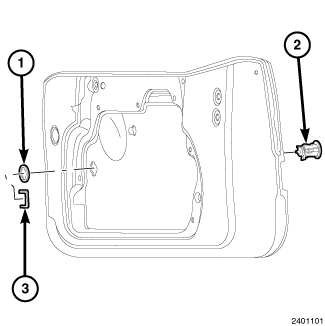
- Assemble gasket (1) onto lock cylinder (2) until fully seated.
-
Install lock cylinder (2) into hole in outer door panel.
NOTE: Cylinder post must point forward.
NOTE: Cylinder drain hole must point down.
-
While holding lock cylinder (2) in place slide retainer clip (3) onto lock cylinder.
-
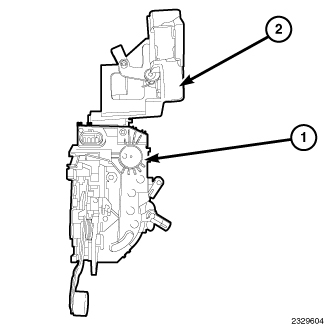
Install the presenter (2) onto the top of the latch assembly (1).
Ensure that the presenter (2) locks into place.
-
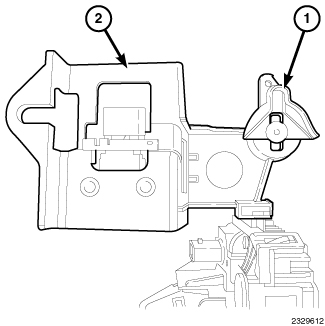
Install bellcrank (1) onto the presenter (2).
-
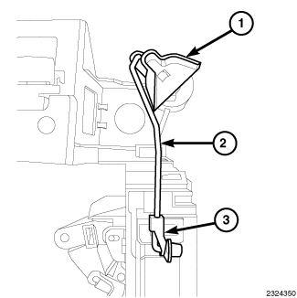
Install the door lock cylinder (bellcrank) to latch link (rod with orange stripe). Insert the end of the link (rod) (2) into the bellcrank (1) and then insert the other end into the orange clip (3).
-
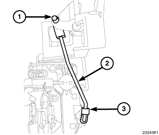
Install the door outside handle to latch link (rod with red stripe). Insert link (rod) (2) into the red clip on the presenter (1) and then on the red clip on the latch assembly (3).
-
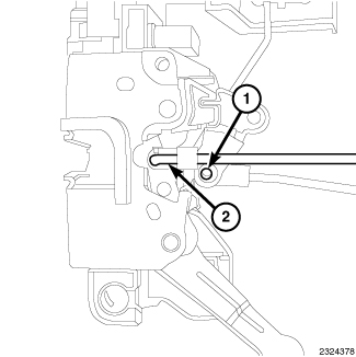
Install the door inside lock to latch (2) and door inside release to latch (1) links (rods).
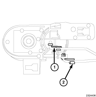
- Install the inside handle to latch link (rod with green stripe) to the inside release handle assembly. The link (1) will attach to the blue retainer.
-
Install the inside lock to latch link (rod with white stripe) to the inside release handle assembly. The link (2) will attach to the black retainer.
-
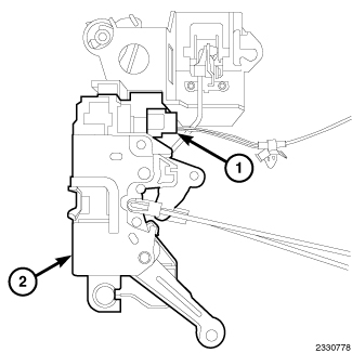
Connect the wiring harness (1) to the latch assembly (2).
-
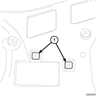
Install the two plastic snap-in nuts (1) to the door.
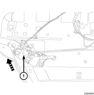
NOTE: Visually verify that the pin on the lock cylinder is engaged with the bell crank.
-
Position the latch assembly (1) (latch, presenter, links, harness and inside handle) to the door.
-
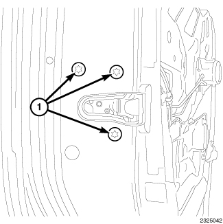
Position and install the latch screws (1) to the door.
Tighten the screws to 8 N·m (71 in. lbs.).
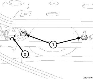
-
Install the exterior door handle to the door. Install the hex nuts (2).
Tighten to 5 N·m (44 in. lbs.).
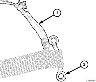
-
Attach the footman loop (2) to the wiring harness (1) check strap.
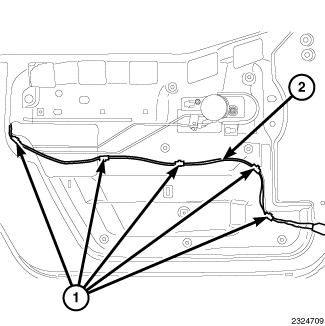
-
Route the wiring harness (2) along the center portion of the door and down the side. Install the wiring harness push pin retainers (1) into the door assembly.
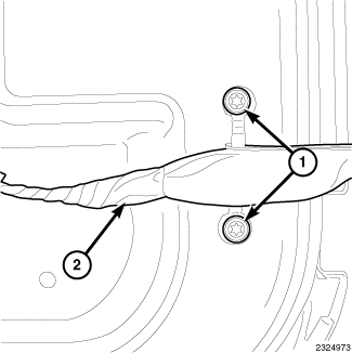
-
Using two screws, install the footman loop to the door.
Tighten the screws to 5 N.m (44 in. lbs.).
-
Install the hinges to the exterior side of the door.
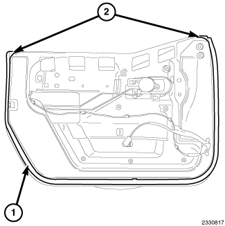
- Install the weatherstrip (1) to the door, attach a weatherstrip retainer (2) to the hole located on the top portion of the door and work towards the opposite side by inserting the weatherstrip (1) into the door channel. When installed, install the second weatherstrip retainer into the hole located on the top portion of the door.
-
Repeat steps for the opposite side door.
CONNECTOR
| NOTE: |
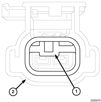
If equipped with power windows and/or locks you must replace the 2 - way connector with the supplied 10 - way connector. |
 |
-
Remove the terminal lock (blue) (1) from the connector (2).
-
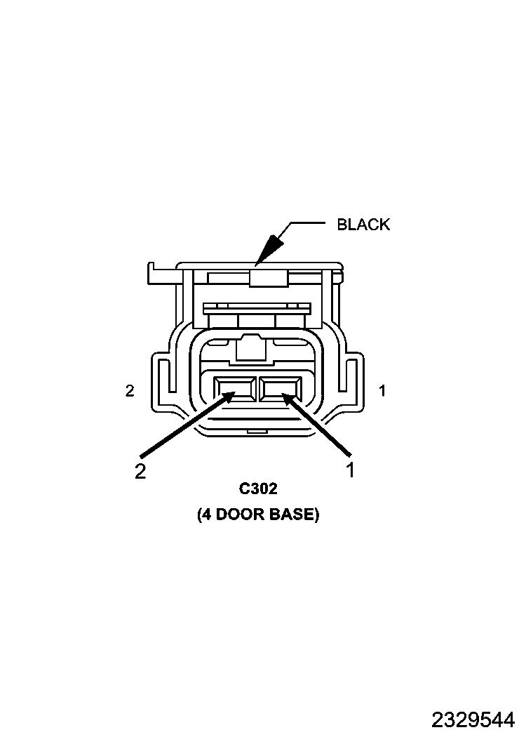
Lift the terminal lock with the appropriate de-pinning tool and remove the wires.
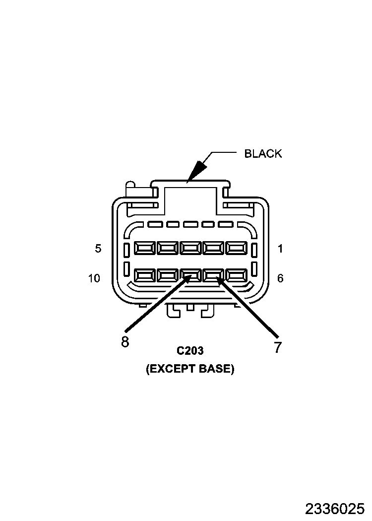
- Insert Pin 1 from 2 - way connector into Pin 7 of the 10 - way connector.
-
Insert Pin 2 from 2 - way connector into Pin 8 of the 10 - way connector.
half door installation
 |
-
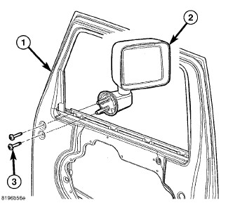
Remove the bolts (3) and separate the mirror (2) from the door (1).
-
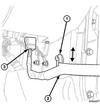
Disconnect the electrical connector (3) at the A-pillar cowl area and separate the check strap (2) from the footman's loop (1).
-
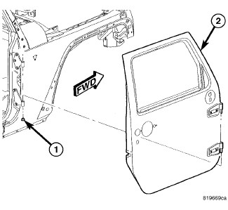
Remove the hinge nuts (1) and lift the door (2) straight up, off the hinges and remove the door.
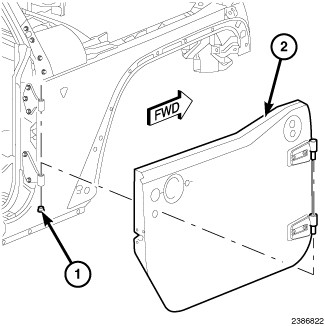
- Align the pins on the door hinges to the holes in the body hinges and position the half door (2) into place.
-
Install the hinge nuts (1).
Tighten to 9 N·m (80 in. lbs.).
-
Install the harness (2) over the footman loop (1) and connect the electrical connector (3).
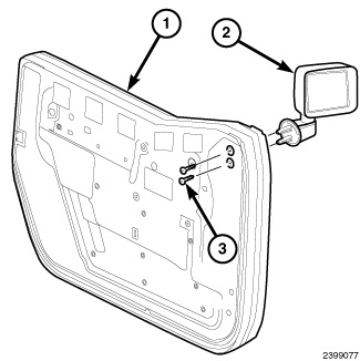
- Install the mirrors to the front door. Tighten the bolts to 13 N·m (10 ft. lbs.).
-
Repeat steps for opposite side.
Door ADJUSTMENT
| NOTE: |
Door adjustment measurements should be taken from stationary or welded body panels like the roof, rocker or quarter panels. |
| NOTE: |
During adjustment procedures, it is recommended that all the hinge fasteners be loosened except for the upper most fasteners. Adjustments can be made using the upper bolts to hold the door with final torque of the fasteners occurring after correct door positioning is achieved. |
| NOTE: |
A suitable body sealant should be used when removing or moving the hinges. |
FORE/AFT
 |
| NOTE: |
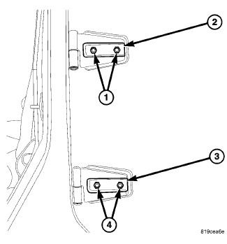
Fore/aft (lateral) door adjustment is done by loosening the hinge to the door fasteners one hinge at a time and moving the door to the correct position. |
- Support the door with a suitable lifting device.
- Loosen the upper (1) and lower (4) hinge to door fasteners.
-
Adjust the door to the correct position.
Tighten the hinge to door bolts to 26 N·m (19 ft. lbs.).
UP/DOWN
 |
| NOTE: |
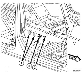
Up/down door adjustment is done by loosening hinge to the hinge pillar fasteners or the hinge to door fasteners and moving the door to the correct position. |
- Support the door with a suitable lifting device.
-
Loosen the latch striker bolts (3).
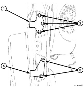
- If necessary, loosen the hinge to hinge pillar fasteners (2) and (3).
-
Tighten the hinge to body fasteners to 28 N·m (21 ft. lbs.).
- If necessary, loosen the hinge to door fasteners (1) and (4).
-
Adjust the door to the correct position.
Tighten the door to hinge fasteners to 26 N·m (19 ft. lbs.).
-
Tighten the latch striker bolts (3) 26 N·m (19 ft. lbs.).
IN/OUT
|
| NOTE: |
In/out door adjustment is done by loosening the hinge to body fasteners one hinge at a time and moving the door to the correct position. |
- Support the door with a suitable lifting device.
-
Loosen the latch striker bolts (3).
- Loosen the hinge to body fasteners (2) and (3),
- Adjust the door to the correct position.
-
Tighten the hinge to body fasteners to 28 N·m (21 ft. lbs.).
-
Tighten the latch striker bolts (3) to 26 N·m (19 ft. lbs.).
BODY GAP SPECIFICATIONS
FRONT DOOR
|
DESCRIPTION |
GAP |
FLUSH |
|---|---|---|
|
Front Door to Body Side |
5.0 mm +/- 1.5 mm |
0.0 mm +/- 1.5 mm |
|
Fender to Door |
5.0 mm +/- 1.5 mm |
0.0 mm +/- 1.5 mm |
REAR 1/2 DOOR KIT
REAR 1/2 DOOR KIT
PROCEDURE STEPS:
JEEP WRANGLER
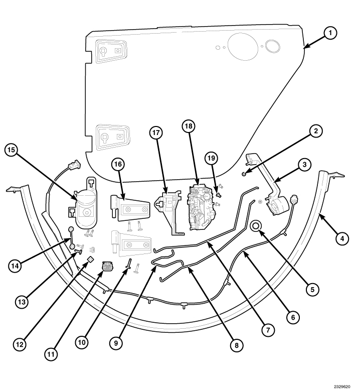 |
REAR DOORS
|
CALL OUT |
DESCRIPTION |
QUANTITY |
|---|---|---|
|
1 |
Door, Rear Half, Left Door, Right Door (Not Shown) |
2 |
|
2 |
Nut, Hex, Exterior Door Handle |
4 |
|
3 |
Handle, Exterior Door, Left Door, Right Door (Not Shown) |
2 |
|
4 |
Weatherseal, Door to Body, Rear Half Door, Left Door, Right Door (Not Shown) |
2 |
|
5 |
Plug |
2 |
|
6 |
Door Harness |
2 |
|
7 |
Link, Inside Release to Latch, Left Door, Right Door (Not Shown) |
2 |
|
8 |
Link, Door Inside Lock to Latch, Left Door, Right Door (Not Shown) |
2 |
|
9 |
Link, Outside Handle to Latch, Left Door, Right Door (Not Shown) |
2 |
|
10 |
Screw (Hinge, Door) |
8 |
|
11 |
6-way Connector, |
2 |
|
12 |
Nut, Plastic Snap-in |
4 |
|
13 |
Screw, Pan Head, M6 X 1 X 20 (Footman Loop)(Inside Handle) |
8 |
|
14 |
Footman Loop, Door Check Strap Half Door |
2 |
|
15 |
Handle, Inside Release, Left Door, Right Door (Not Shown) |
2 |
|
16 |
Hinge, Door, Left Door, Right Door (Not Shown) |
4 |
|
17 |
Presenter, Latch, Rear Door, Left Door, Right Door (Not Shown) |
2 |
|
18 |
Latch, Rear Door, Left Door, Right Door (Not Shown) |
2 |
|
19 |
Screw (Latch) |
6 |
DOOR SUB-ASSEMBLY
| NOTE: |
For ease in installation, it is recommended that the latch components, wiring harness and interior handle are assembled as an assembly prior to installation. |
| NOTE: |
The links (rods) must be installed with the colored stripe (located on the rod) towards the latch assembly. Install the links to the latch's color coordinated retainer unless otherwise noted. |
-
Paint the door and door hinges to match body color.
-
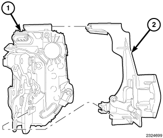
Install the presenter (2) to the top of the latch (1). Ensure that the presenter (2) locks into place.
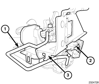
- Install the outside handle to latch link (rod with red stripe) (1) to the latch (2).
-
Install the outside handle to latch link (rod with red stripe) (1) to the presenter (3).
-
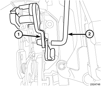
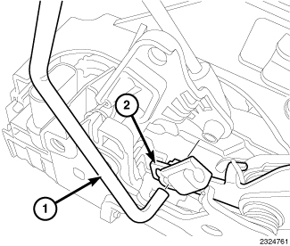
Install the inside lock to latch link (rod with white stripe) (2) to the latch assembly (1).
-
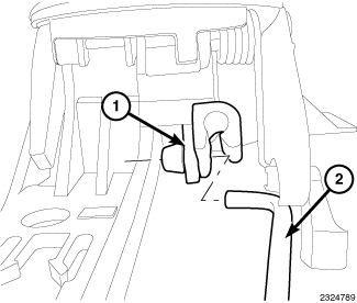
Install the inside handle to latch link (rod with green stripe) (1) to the latch assembly (2).
-
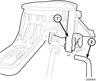
Install the inside lock to latch link (rod with white stripe) (2) to the inside release handle assembly (1). The link (2) will attach to the black retainer.
-
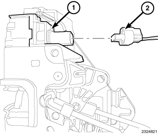
Install the inside handle to latch link (rod with green stripe) (2) to the inside release handle assembly (1) . The link (1) will attach to the blue retainer.
-
Connect the wiring harness (2) to the latch (1).
-
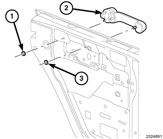
Install the exterior door handle (2) to the door.
Tighten the nuts (1, 3) to 5 N.m (44 in. lbs.).
-
Install the two plastic snap-in nuts (1) to the door.
-
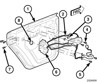
Position the latch assembly (latch, presenter, links, harness and inside handle) (6) to the door (1).
NOTE: The wiring harness (2) will need be fed through the access hole nearest the latch area.
-
Route the wiring harness (2) along the upper portion of the door (1) and down the side. Install the wiring harness push pin retainers into the door assembly.
NOTE: If vehicle is equipped with power windows/locks, the harness connector will need to be removed and replaced.
- Position and install the inside release handle screws (4) to the door (1). Tighten the screws (4) to 5 N.m (44 in. lbs.).
-
Install the plug (8) to the door (1).
-
Position and install the latch screws (1) to the door.
Tighten the screws (6) to 8 N.m (71 in. lbs.).
-
Attach the footman loop (2) to the wiring harness (1) check strap.
- Using two screws (1), install the footman loop to the door. Tighten the screws (1) to 5 N.m (44 in. lbs.).
-
Install the hinges to the exterior side of the door.
Hand tighten the bolts .
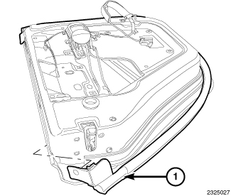
- Install the weatherstrip (1) to the door, attach a weatherstrip retainer to the hole located on the top portion of the door and work towards the opposite side by inserting the weatherstrip (1) into the door channel. When installed, install the second weatherstrip retainer into the hole located on the top portion of the door.
-
Repeat steps for the opposite side door.
CONNECTOR
|
| NOTE: |
If equipped with power windows and/or locks you must replace the 2 - way connector with the supplied 6 - way connector. |
-
Remove the terminal lock (blue) (1) from the connector (2).
-
Lift the terminal lock with the appropriate de-pinning tool and remove the wires.
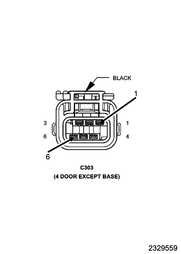
- Insert Pin 1 from the 2 - way connector to Pin 1 on the 6 - way connector.
-
Insert Pin 2 from the 2 - way connector to Pin 6 on the 6 - way connector.
HALF DOOR INSTALLATION
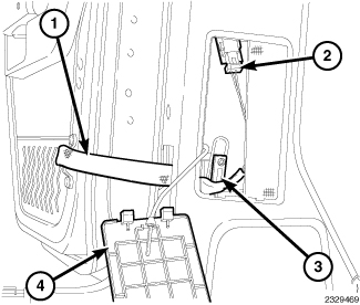 |
- Remove the access door (4) from the interior B-Pillar lower trim.
- Disconnect the door harness connector (2).
- Remove the door harness from the footman loop (3) on the B-Pillar.
-
Pull the door harness (1) out towards the rear of the vehicle through the opening in the interior B-Pillar lower trim side.
-
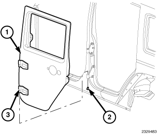
Remove the hinge nuts (2), lift the door (1) straight up off the body hinges and remove the door (1).
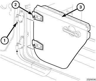
- Align the pins on the door hinges (2) to the holes in the body hinges and position the half door (3) into place.
-
Install the hinge nuts (1).
Tighten the hinge nuts (1) to 9 N·m (80 in. lbs.).
- Route the wiring harness (1) through the interior B-Pillar lower trim side.
- Install the harness (1) to the footman loop (3) on the B-Pillar.
- Connect the door harness (2) to the body harness.
- Install the access door (4) to the B-Pillar lower trim.
-
Repeat steps for opposite side.
DOOR ADJUSTMENT
| NOTE: |
Door adjustment measurements should be taken from stationary or welded body panels like the roof, rocker or quarter panels. |
| NOTE: |
During adjustment procedures, it is recommended that all the hinge fasteners be loosened except for the upper most fasteners. Adjustments can be made using the upper bolts to hold the door with final torque of the fasteners occurring after correct door positioning is achieved. |
| NOTE: |
A suitable body sealant should be used when removing or moving the hinges. |
FORE/AFT
|
| NOTE: |
Fore/aft (lateral) door adjustment is done by loosening the hinge to the door fasteners one hinge at a time and moving the door to the correct position. |
- Support the door with a suitable lifting device.
- Loosen the upper (1) and lower (4) hinge to door fasteners.
- Adjust the door to the correct position.
-
Tighten the hinge to door bolts to 26 N·m (19 ft. lbs.).
UP/DOWN
|
| NOTE: |
Up/down door adjustment is done by loosening hinge to the hinge pillar fasteners or the hinge to door fasteners and moving the door to the correct position. |
| NOTE: |
Front door opening shown, rear door opening similar. |
- Support the door with a suitable lifting device.
-
Loosen the latch striker bolts (3).
-
If necessary, loosen the hinge to body fasteners (2, 3).
Tighten the hinge to body fasteners (2, 3) to 28 N·m (21 ft. lbs.).
- If necessary, loosen the hinge to door fasteners (1) and (4).
-
Adjust the door to the correct position.
Tighten the door to hinge fasteners to 26 N·m (19 ft. lbs.).
-
Tighten the latch striker bolts (3) 26 N·m (19 ft. lbs.).
IN/OUT
|
| NOTE: |
In/out door adjustment is done by loosening the hinge to body fasteners one hinge at a time and moving the door to the correct position. |
| NOTE: |
Front door opening shown, rear door opening similar. |
- Support the door with a suitable lifting device.
-
Loosen the latch striker bolts (3).
- Loosen the hinge to body fasteners (2, 3).
-
Adjust the door to the correct position.
Tighten the hinge to body fasteners (2, 3) to 28 N·m (21 ft. lbs.).
-
Tighten the latch striker bolts (3) to 26 N·m (19 ft. lbs.).
BODY GAP SPECIFICATIONS
REAR DOOR
|
DESCRIPTION |
GAP |
FLUSH |
|---|---|---|
|
Rear Door to Body Side |
5.0mm +/- 1.5mm |
0.0mm +/- 1.5mm |