Fog Lights And Electrical
FOG LAMP KIT
FOG LAMP KIT
JEEP WRANGLER
 |
|
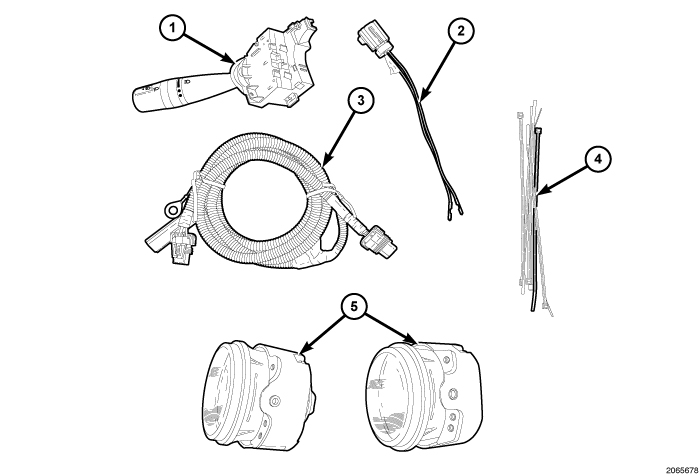
CALL OUT |
DESCRIPTION |
QUANTITY |
|---|---|---|
|
1 |
Multi-function Switch |
1 |
|
2 |
TIPM Jumper Harness |
1 |
|
3 |
Fog Lamp Wire Harness |
1 |
|
4 |
Zip Ties |
6 |
|
5 |
Fog Lamp |
2 |
PROCEDURE STEPS:
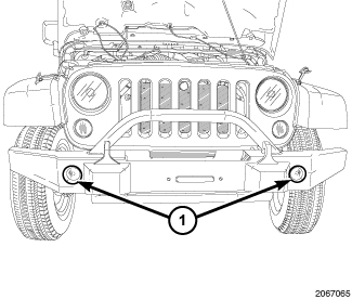
FOG LAMP INSTALLATION
 |
NEW MULTI-FUNCTION SWITCH INSTALLATION
To avoid serious or fatal injury on vehicles equipped with airbags, disable the Supplemental Restraint System (SRS) before attempting any steering wheel, steering column, airbag, seat belt tensioner, impact sensor or instrument panel component diagnosis or service. Disconnect and isolate the battery negative (ground) cable, then wait two minutes for the system capacitor to discharge before performing further diagnosis or service. This is the only sure way to disable the SRS. Failure to take the proper precautions could result in accidental airbag deployment.
WARNING:
 |
- Disconnect the negative battery cable.
-
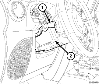
Remove the three screws from lower shroud. Remove both the upper (1) and lower (2) shrouds from the steering column.
.
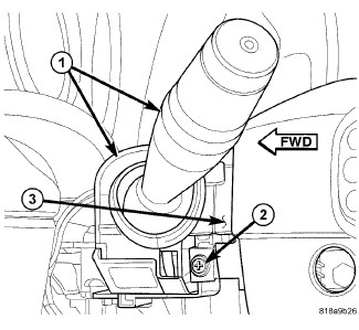
- Disconnect the instrument panel wire harness connector from the connector receptacle on the back of the left multi-function switch.
- Remove the screw (2) that secures the left multi-function switch (1) to the mounting bracket integral to the left side of the clockspring (3) on the steering column.
- Slide the switch away from the clockspring far enough to disengage the slide tabs on the switch housing from the channel formations in the mounting bracket.
- Disconnect the jumper wire harness connector from the connector receptacle on the inboard end of the left multi-function switch.
- Remove the switch from the clockspring.
- Position the new left multi-function switch (1) close enough to the mounting bracket (3) integral to the left side of the clockspring to reconnect the jumper wire harness connector to the connector receptacle on the inboard side of the switch housing.
- Align the slide tabs on the switch housing with the channel formations integral to the clockspring mounting bracket, then slide the switch into the bracket until it is firmly seated.
- Install and tighten the screw (2) that secures the mounting tab on the front of the left multi-function switch to the mounting bracket on the clockspring. Tighten the screw to 1 N·m (10 in. lbs.).
-
Reconnect the instrument panel wire harness connector to the connector receptacle on the back of the switch housing.
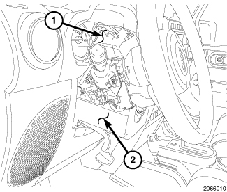
- Position both the upper (1) and lower (2) shrouds on the steering column.
-
Install the three screws in the lower shroud (2).
WIRE HARNESS INSTALLATION
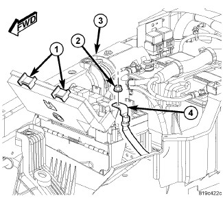 |
- Release the Totally Integrated Power Module (TIPM) cover retaining clips (1) and open the TIPM cover.
-
Remove the TIPM positive cable retaining nut (2) and remove the cable (4) from the stud.
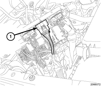
- Position the TIPM back to gain access to the "D" connector (1) under the TIPM.
-
Disconnect the "D" connector (1).
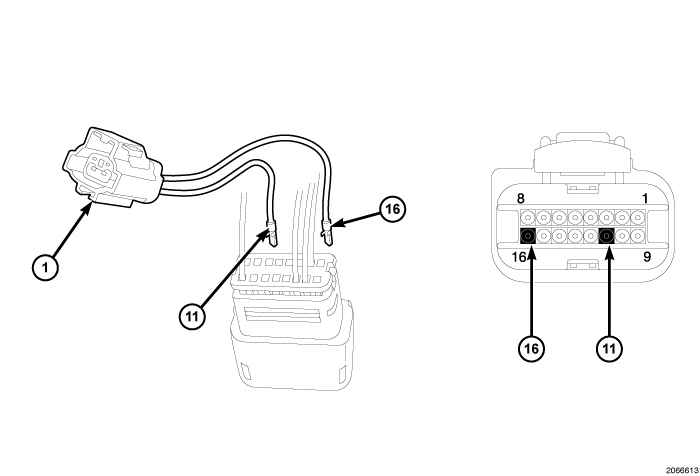
- Pull back the locking wedge on the back of the "D" connector and remove the plastic pins in cavity 11 and 16.
- Insert the WT/OR wire from the supplied jumper harness (1) into the back of the "D" connector cavity 11.
- Insert the WT/YL wire from the supplied jumper harness (1) into the back of the "D" connector cavity 16.
- Push the locking wedge forward on the "D" connector to lock the wires in the connector.
-
Connect the "D" connected back into the TIPM.
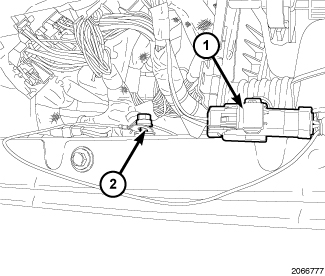
- Connect the fog lamp wire harness to the TIPM jumper harness (1).
-
Install the ground wire (2) for the fog lamp wire harness.
- Position the TIPM onto the mounting bracket and push down until the mounting clips are fully seated.
-
Position the TIPM positive cable (4) onto the mounting stud and install the retaining nut (2). Tighten the nut to 9 - 11 N·m (80 - 100 in. lbs.).
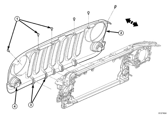
- Remove the grill by twisting the center of the six push pin fastener (1) inserts. This will allow the pin to release and to be removed.
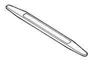
- Using a trim stick C-4755 or equivalent, Release the lower clips (3) and separate the grille from the front end module.
-
Disconnect the electrical connectors (4).
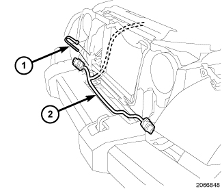
- Route the fog lamp wire harness (2) to the fog lamps and secure using zip ties (1).
-
Connect the fog lamp wire harness connectors to the fog lamps.
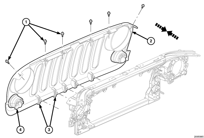
- Install the grill by connecting the electrical connectors (4).
- Position the grille (2) onto the front end module and seat the clips (3) fully.
- Install the push pin fasteners (1).
-
Connect the negative battery cable.
UPDATE VEHICLE CONFIGURATION
- VIN must be updated with the sales code of the added accessory in order to enable system functionality. Using the DealerCONNECT website and a StarMobile diagnostic tool, complete the vehicle configuration.
- Log on to https://dealerconnect.chrysler.com
- In the “Vehicle Option” screen under the “Global Claims System” category in the “Service” tab, enter vehicle VIN and add sales code(s) noted below as a “Dealer Installed Option”. LNJ (Fog Lamps)
- Confirm that the new sales code has been successfully added to the VIN.
- With the StarMobile diagnostic tool connected to both the internet (via Ethernet port or wireless connection) and the vehicle, perform the following steps from the Initial Start Up Screen:
- Select "VEHICLE PREPARATION"
- Select "RESTORE VEHICLE CONFIGURATION"
- Select "START"
- Select "NEXT"
- If necessary, select proper vehicle line and model year and select "NEXT"
- Confirm correct selection and select "NEXT"
- Enter vehicle VIN using On-Screen keyboard or confirm that auto-filled VIN plate and select "NEXT"
- Select "OK"
- Enter user ID, password and dealer code using On-Screen keyboard and Select "OK"
- Wait for vehicle configuration data to be downloaded and select "NEXT"
- Select "NEXT"
- Confirm that vehicle configuration has been programmed successfully
- Note On-Screen instructions and select "FINISH"
VALIDATION PROCESS
- Select "ECU VIEW"
- Select "TIPM/CGW"
- Select "MORE OPTIONS"
- Select "ECU DETAILS"
- Select "CONFIG INFO"
- Toggle down, verify:
|
NAME |
VALUE |
|---|---|
|
FOG LAMPS PRESENT |
SET |