Front Axle - 216FBI
- DIAGNOSIS AND TESTING - FRONT AXLE - 216FBI
- ADJUSTMENTS
- SPECIFICATIONS
- REMOVAL
- INSTALLATION
- SPECIAL TOOLS
DIAGNOSIS AND TESTING - FRONT AXLE - 216FBI
DIAGNOSIS AND TESTING - FRONT AXLE - 216FBI
DIAGNOSTIC CHART
|
Condition |
Possible Causes |
Correction |
|---|---|---|
|
Wheel Noise |
1. Wheel loose. |
1. Tighten loose nuts. |
|
2. Faulty, brinelled wheel bearing. |
2. Replace bearing. |
|
|
Axle Shaft Noise |
1. Misaligned axle tube. |
1. Inspect axle tube alignment. Correct as necessary. |
|
2. Bent or sprung axle shaft. |
2. Inspect and correct as necessary. |
|
|
3. End play in pinion bearings. |
3. Refer to pinion pre-load information and correct as necessary. |
|
|
4. Excessive ring and pinion gear backlash. |
4. Check and adjustment ring and pinion gear backlash. |
|
|
5. Improper pinion bearing adjustments. |
5. Adjust the pinion bearings pre-load. |
|
|
6. Loose pinion flange nut. |
6. Tighten pinion flange nut to specifications. |
|
|
7. Scuffed gear tooth contact surfaces. |
7. Inspect and replace as necessary. |
|
|
Axle Shaft Broke |
1. Misaligned axle tube. |
1. Replace broken shaft after correcting tube mis-alignment. |
|
2 Vehicle overloaded. |
2. Replace broken shaft and avoid excessive weight on vehicle. |
|
|
3. Erratic clutch operation. |
3. Replace broken shaft and avoid or correct erratic clutch operation. |
|
|
4. Grabbing clutch. |
4. Replace broken shaft and inspect and repair clutch as necessary. |
|
|
Differential Cracked |
1. Improper differential bearing adjustment. |
1. Replace case, inspect gears and bearings for further damage. Set differential bearing pre-load properly. |
|
2. Excessive ring gear backlash. |
2. Replace case and inspect gears and bearings for further damage. Set ring gear backlash. |
|
|
3. Vehicle overloaded. |
3. Replace case and inspect gears and bearings for further damage. Avoid excessive vehicle weight. |
|
|
4. Erratic clutch operation. |
4. Replace case and inspect gears and bearings for further damage. Avoid erratic use of clutch. |
|
|
Differential Gears Scored |
1. Insufficient lubrication. |
1. Replace scored gears. Fill differential with the correct fluid type and quantity. |
|
2. Improper grade of lubricant. |
2. Replace scored gears. Fill differential with the correct fluid type and quantity. |
|
|
3. Excessive spinning of one wheel/tire. |
3. Replace scored gears. Inspect all gears, pinion bores, and shaft for damage. Service as necessary. |
|
|
Loss Of Lubricant |
1. Lubricant level too high. |
1. Drain lubricant to the correct level. |
|
2. Worn axle shaft seals. |
2. Replace seals. |
|
|
3. Cracked differential housing. |
3. Repair as necessary. |
|
|
4. Worn pinion seal. |
4. Replace seal. |
|
|
5. Worn/scored flange. |
5. Replace flange and seal. |
|
|
6. Differential cover not sealed. |
6. Remove, clean, and seal cover. |
|
|
Axle Overheating |
1. Lubricant level low. |
1. Fill differential to correct level. |
|
2. Improper grade of lubricant. |
2. Fill differential with the correct fluid type and quantity. |
|
|
3. Bearing pre-loads too high. |
3. Adjust bearing pre-loads. |
|
|
4. Insufficient ring gear backlash. |
4. Adjust ring gear backlash. |
|
|
Gear Teeth Broke |
1. Overloading. |
1. Replace gears. Examine other gears and bearings for possible damage. |
|
2. Erratic clutch operation. |
2. Replace gears and examine the remaining parts for damage. Avoid erratic clutch operation. |
|
|
3. Ice-spotted pavement. |
3. Replace gears and examine remaining parts for damage. |
|
|
4. Improper adjustments. |
4. Replace gears and examine remaining parts for damage. Ensure ring gear backlash is correct. |
|
|
Axle Noise |
1. Insufficient lubricant. |
1. Fill differential with the correct fluid type and quantity. |
|
2. Improper ring and pinion gear adjustment. |
2. Check ring and pinion gear contact pattern. |
|
|
3. Unmatched ring gear and pinion. |
3. Replace gears with a matched ring gear and pinion. |
|
|
4. Worn teeth on ring and pinion gears. |
4. Replace ring and pinion gears. |
|
|
5. Loose pinion bearings. |
5. Adjust pinion bearing pre-load. |
|
|
6. Loose differential bearings. |
6. Adjust differential bearing pre-load. |
|
|
7. Loose or sprung ring gear. |
7. Measure ring gear run-out. Replace components as necessary. |
|
|
8. Loose differential bearing cap bolts. |
8. Inspect differential components and replace as necessary. Ensure bearing caps are torqued to the proper specification. |
|
|
9. Housing not machined properly. |
9. Replace housing. |
GEAR NOISE
Axle gear noise can be caused by insufficient lubricant, incorrect backlash, tooth contact, worn/damaged gears or the carrier housing not having the proper offset and squareness.
Gear noise usually happens at a specific speed range. The noise can also occur during a specific type of driving condition. These conditions are acceleration, deceleration, coast, or constant load.
When road testing, first warm-up the axle fluid by driving the vehicle at least 5 miles and then accelerate the vehicle to the speed range where the noise is the greatest. Shift out-of-gear and coast through the peak-noise range. If the noise stops or changes greatly:
Differential side gears and pinions can be checked by turning the vehicle. They usually do not cause noise during straight-ahead driving when the gears are unloaded. The side gears are loaded during vehicle turns. A worn pinion mate shaft can also cause a snapping or a knocking noise.
BEARING NOISE
The axle shaft, differential and pinion bearings can all produce noise when worn or damaged. Bearing noise can be either a whining, or a growling sound.
Pinion bearings have a constant-pitch noise. This noise changes only with vehicle speed. Pinion bearing noise will be higher pitched because it rotates at a faster rate. Drive the vehicle and load the differential. If bearing noise occurs, the rear pinion bearing is the source of the noise. If the bearing noise is heard during a coast, the front pinion bearing is the source.
Differential bearings usually produce a low pitch noise. Differential bearing noise is similar to pinion bearing noise. The pitch of differential bearing noise is also constant and varies only with vehicle speed.
Axle shaft bearings produce noise and vibration when worn or damaged. The noise generally changes when the bearings are loaded. Road test the vehicle. Turn the vehicle sharply to the left and to the right. This will load the bearings and change the noise level. Where axle bearing damage is slight, the noise is usually not noticeable at speeds above 30 mph.
LOW SPEED KNOCK
Low speed knock is generally caused by a worn U-joint/CV or by worn side-gear thrust washers. A worn pinion shaft bore will also cause low speed knock.
VIBRATION
Vibration at the rear of the vehicle is usually caused by:
- Damaged drive shaft.
- Missing drive shaft balance weight(s).
- Worn or out of balance wheels.
- Loose wheel lug nuts.
- Worn U-joint or CV.
- Loose/broken springs.
- Damaged axle shaft bearing(s).
- Loose pinion gear nut.
- Excessive pinion flange run out.
- Bent axle shaft(s).
Check for loose or damaged front end components or engine/transmission mounts. These components can contribute to what appears to be a rear end vibration. Do not overlook engine accessories, brackets and drive belts.
All driveline components should be examined before starting any repair.
DRIVELINE SNAP
A snap or clunk noise when the vehicle is shifted into gear (or the clutch engaged) can be caused by:
- High engine idle speed.
- Transmission shift operation.
- Loose engine/transmission/transfer case mounts.
- Worn U-joints or CV.
- Loose spring mounts.
- Loose pinion gear nut and flange.
- Excessive ring gear backlash.
- Excessive side gear to case clearance.
The source of a snap or a clunk noise can be determined with the assistance of a helper. Raise the vehicle on a hoist with the wheels free to rotate. Instruct the helper to shift the transmission into gear. Listen for the noise, a mechanics stethoscope is helpful in isolating the source of a noise.
ADJUSTMENTS
ADJUSTMENTS
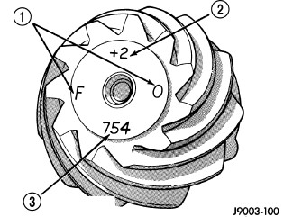 |
Ring and pinion gears are supplied as matched sets. The identifying numbers (3) for the ring and pinion gear are etched into the each gear. A plus (+) number, minus (-) number or zero (0) is etched into the face of the pinion gear (2). This number is the amount (in thousandths of an inch) the depth varies from the standard depth setting of a pinion etched with a (0). The standard depth provides the best gear tooth contact pattern. Refer to Backlash and Contact Pattern in this section for additional information.
If a new gear set is being installed, note the depth variance etched into both the original and replacement pinion. Add or subtract this number from the thickness of the original depth shim/oil slinger to compensate for the difference in the depth variances. Refer to the Depth Variance chart.
Note where Old and New Pinion Marking columns intersect. Intersecting figure represents plus or minus the amount needed.
Note the etched number on the face of the pinion gear head (-1,
-2, 0, +1, +2, etc.). The numbers represent thousands of an inch deviation
from the standard. If the number is negative, add that value to the
required thickness of the depth shims. If the number is positive,
subtract that value from the thickness of the depth shim. If the number
is 0 no change is necessary.
PINION GEAR DEPTH VARIANCE
|
Original Pinion Gear Depth Variance |
Replacement Pinion Gear Depth Variance |
|||||||||
|---|---|---|---|---|---|---|---|---|---|---|
|
−4 |
−3 |
−2 |
−1 |
0 |
+1 |
+2 |
+3 |
+4 |
||
|
+4 |
+0.008 |
+0.007 |
+0.006 |
+0.005 |
+0.004 |
+0.003 |
+0.002 |
+0.001 |
0 |
|
|
+3 |
+0.007 |
+0.006 |
+0.005 |
+0.004 |
+0.003 |
+0.002 |
+0.001 |
0 |
−0.001 |
|
|
+2 |
+0.006 |
+0.005 |
+0.004 |
+0.003 |
+0.002 |
+0.001 |
0 |
−0.001 |
−0.002 |
|
|
+1 |
+0.005 |
+0.004 |
+0.003 |
+0.002 |
+0.001 |
0 |
−0.001 |
−0.002 |
−0.003 |
|
|
0 |
+0.004 |
+0.003 |
+0.002 |
+0.001 |
0 |
−0.001 |
−0.002 |
−0.003 |
−0.004 |
|
|
−1 |
+0.003 |
+0.002 |
+0.001 |
0 |
−0.001 |
−0.002 |
−0.003 |
−0.004 |
−0.005 |
|
|
−2 |
+0.002 |
+0.001 |
0 |
−0.001 |
−0.002 |
−0.003 |
−0.004 |
−0.005 |
−0.006 |
|
|
−3 |
+0.001 |
0 |
−0.001 |
−0.002 |
−0.003 |
−0.004 |
−0.005 |
−0.006 |
−0.007 |
|
|
−4 |
0 |
−0.001 |
−0.002 |
−0.003 |
−0.004 |
−0.005 |
−0.006 |
−0.007 |
−0.008 |
|
PINION DEPTH MEASUREMENT
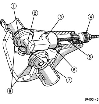 |
Measurements are taken with pinion bearing cups and pinion bearings installed in the housing. Take measurements with Dial Indicator C-3339A (1).
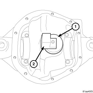 |
- Assemble Pinion Height Block 6739 (2), Pinion Block 9990 (1) and rear pinion bearing onto Screw 6741 .
- Insert assembled height gauge components, rear bearing and screw into the housing through pinion bearing cups.
-
Install front pinion bearing and Cone-nut 6740 . Tighten nut until a Torque To Rotate the screw is 2.25 N·m (20 in. lbs.).
-
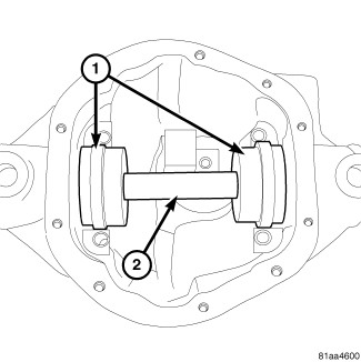
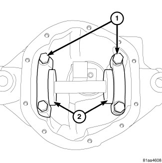
Place Arbor Disc 8541A (1) on Arbor D-115-3 (2) in position in the housing side bearing cradles .
NOTE: Arbor Discs 8541A has different step diameters to fit other axles. Choose proper step for axle being serviced.
-
Install differential bearing caps (1) on arbor discs (2) and install bearing cap bolts. Tighten bearing cap bolts to 108 N·m (80 ft. lbs.).
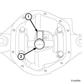
- Assemble Scooter Block D-115-2A (1) and Dial Indicator C-3339A (2) secure set screw.
- Position Scooter Block/Dial Indicator flush on the pinion height block. Hold scooter block and zero the dial indicator.
- Slowly slide the scooter block (1) across the pinion height block over to the arbor. Move the scooter block till dial indicator (2) crests the arbor, then record the highest reading.
-
Select a shim equal to the dial indicator reading plus or minus the pinion depth variance number etched in the face of the pinion. Example: If the depth variance is -2, add 0.002 in. to the dial indicator reading. If the depth variance is +2, subtract 0.002 in. from the dial indicator reading.
The total is the shim thickness needed for the pinion depth variance.
DIFFERENTIAL BEARING PRELOAD AND GEAR BACKLASH
 |
Before performing differential bearing preload and ring gear backlash measurements, pinion gear depth must be established and the pinion gear ready for installation. Establishing pinion gear depth is essential to gear backlash and tooth contact patterns.
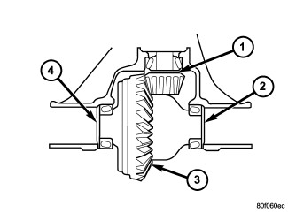
Differential bearing preload and gear backlash is accomplish with selective shims (2,4) positioned behind the differential side bearing cups. Shim thickness is determined using Dummy Bearings 9992 in place of the differential side bearings and a Dial Indicator C-3339A .
SHIM FORMULA: Differential End Play + Preload Specification = Total Differential Shim. Total Differential Shim - Ring Gear Side Shim - Backlash Specification = Pinon Gear Side Shim.
 |
- Remove differential side bearings from differential case.
- Remove factory installed shims from differential case.
- Install ring gear on differential case and tighten bolts to specification.
- Install dummy side bearings 9992 on differential case.
- Install differential case (3) in the housing (2).
- Record the thickness of Dummy Shims 10178 , then insert the shims between the dummy bearings and the differential housing.
-
Install bearing caps (1) in original location and snug the bolts.
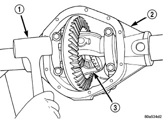
-
Seat differential (3) dummy bearings to pinion side (2) of the housing with a dead-blow hammer (1).
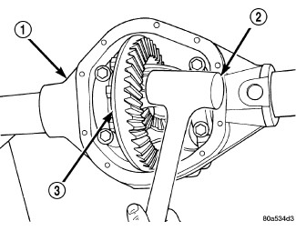
-
Seat differential (3) dummy bearings to ring gear side (1) of the housing with a dead-blow hammer (2).
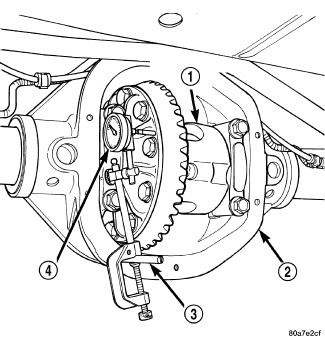
- Thread Pin C-3288-B (3) into cover bolt hole below ring gear.
-
Attach the Dial Indicator C-3339A (4) to the pin. Position the dial indicator plunger on a flat surface between the ring gear bolt heads.
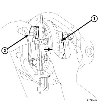
-
Push and hold differential case (1) to pinion gear side of the housing and zero dial indicator (2).
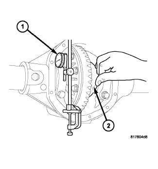
- Push and hold differential case (2) to ring gear side of the housing. Record dial indicator (1) differential reading. Add preload specification 0.25 mm (0.010 in) to differential dial indicator reading. This is the total shims needed to preload the differential bearings. EXAMPLE: Differential Dial Indicator Reading + Preload Specification 0.25 mm (0.010 in) = Total Differential Shim
- Rotate dial indicator out of the way on the pilot stud.
- Remove differential case and dummy bearings from the housing.
-
Install pinion gear in the housing and establish pinion torque to rotating (PTTR).
- Install differential case and dummy bearings 9992 in the housing.
- Install a single dummy shim in the ring gear side. Install the bearing caps and snug bolts.
- Seat ring gear side dummy bearing.
- Position dial indicator (2) plunger on a flat surface between the ring gear bolts.
-
Push and hold differential case (1) against pinion gear and zero dial indicator (2).
- Push and hold differential case (2) to ring gear side of the housing and record dial indicator (1) ring gear side reading.
- Subtract backlash specification 0.05 mm (0.002 in.) from ring gear side reading for ring gear backlash. The remainder is the shim needed for the ring gear side of the differential. EXAMPLE: Ring Gear Side Dial Indicator Reading - Backlash Specification 0.05 mm (0.002 in.) = Ring Gear Side Shim
- Subtract ring gear side shim from the total preload shim. The is the shim needed on the pinion side of the differential. EXAMPLE: Total Differential Shim - Ring Gear Side Shim = Pinion Gear Side Shim
- Rotate dial indicator out of the way on pilot stud.
- Remove differential case and dummy bearings from the housing.
-
Install side bearings on differential case.
-
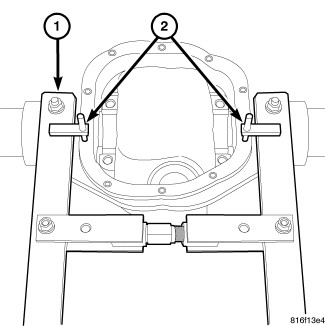
Install Spreader W-129-B (1) with hold downs (2) from Adapter Set 6987B on the housing and spread open enough to receive differential case.
CAUTION: Never spread housing over 0.50 mm (0.020 in). Failure to follow these instructions will damage the housing.
-
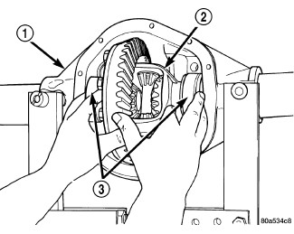
Install differential case (2) into the housing with bearing cups (3) and shims.
- Install bearing caps and tighten bolts finger tight. Remove spreader from the housing.
- Install bearing cap (1) and tighten bolts to 108 N·m (80 ft. lbs.).
-
Rotate the differential case several times to seat the side bearings.
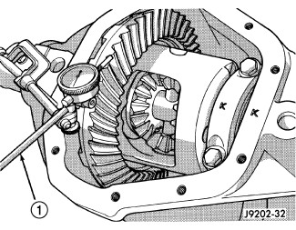
- Position dial indicator plunger against a ring gear tooth.
- Push and hold ring gear upward while not allowing the pinion gear to rotate.
- Zero dial indicator (1) face to pointer.
-
Push and hold ring gear downward while not allowing the pinion gear to rotate. Dial indicator reading should be between 0.12 mm - 0.20 mm (0.005 in - 0.008 in). If backlash is not within specifications transfer the necessary amount of shim thickness from one side of the housing to the other.
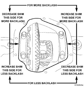
- Verify differential case and ring gear runout by measuring ring to pinion gear backlash at eight locations around the ring gear. Readings should not vary more than 0.05 mm (0.002 in). If readings vary more than specified, the ring gear or the differential case is defective.
After the proper backlash is achieved, perform Gear Contact Pattern Analysis procedure.
GEAR CONTACT PATTERN
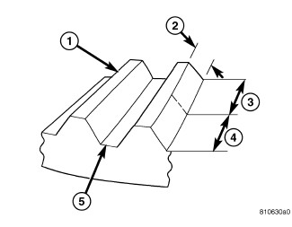 |
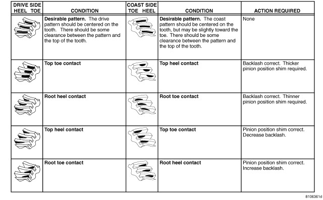
The ring gear and pinion teeth contact patterns will show if the pinion depth is correct in the housing. It will also show if the ring gear backlash has been adjusted correctly. The backlash can be adjusted within specifications to achieve desired tooth contact patterns.
The TOP LAND (1) of the gear tooth is the top surface of the tooth. The PROFILE (2) of the gear tooth is the depth of the tooth. The TOE (3) of the gear is the portion of the tooth surface at the end towards the center. The HEEL (4) of the gear is the portion of the tooth at the outer-end. The ROOT (5) of the gear tooth is the lowest portion of the tooth .
| NOTE: |
If the PROFILE across the tooth is the same it is a Three Axis cut gear. If the PROFILE across the tooth is tapered it is a Two Axis cut gear. |
- Apply a thin coat of hydrated ferric oxide or equivalent to the drive and coast side of the ring gear teeth.
- Wrap, twist and hold a shop towel around the pinion yoke to increase the turning resistance of the pinion. This will provide a more distinct contact pattern.
-
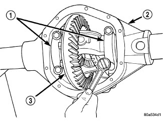
With a boxed end wrench on the ring gear bolt, rotate the differential case one complete revolution in both directions while a load is being applied from shop towel.
The areas on the ring gear teeth with the greatest degree of contact against the pinion teeth will squeegee the compound to the areas with the least amount of contact. Note and compare patterns on the ring gear teeth to Gear Tooth Contact Patterns chart adjust pinion depth and gear backlash as necessary.
 |
TWO or THREE AXIS CUT GEAR
DIFFERENTIAL BEARING PRELOAD CHECK
The final check on the differential assembly before installing the axle shafts is torque to rotate pinion and differential combined. This will verify the correct differential bearing preload.
Total Torque To Rotate (TTTR) is: Pinion Torque To Rotate plus 0.79 - 1.24 N·m (7 - 11 in lbs).
| NOTE: |
If TTTR is high, decrease the shim thickness equally on both sides of the differential and check TTTR again. If TTTR is low, increase the shims thickness equally on both sides of the differential and check TTTR again. |
SPECIFICATIONS
SPECIFICATIONS
AXLE
| DESCRIPTION | SPECIFICATION |
|---|---|
|
Axle Ratio |
4.10 |
|
Ring Gear Diameter |
216 mm (8.5 in.) |
|
Ring Gear Runout |
0.12 (0.005 in.) |
|
Ring Gear Backlash |
0.12 - 0.20 mm (0.005 - 0.008 in.) |
|
Pinion Torque To Rotate - Original Bearing |
1 - 2.2 N·m (10 - 20 in. lbs.) |
|
Pinion Torque To Rotate - New Bearing |
2.2 - 4.5 N·m (20 - 40 in. lbs.) |
|
Total Torque To Rotate: Pinion Torque To Rotate plus |
0.79 - 1.24 N·m (7 - 11 in lbs) |
TORQUE
| DESCRIPTION | N·m |
Ft. Lbs. |
In. Lbs. |
|---|---|---|---|
|
Fill Plug |
34 |
25 |
- |
|
Differential Cover Bolts |
41 |
30 |
- |
|
Bearing Cap Bolts |
108 |
80 |
- |
|
Pinion Nut |
217-271 |
160-200 |
- |
|
Ring Gear Bolts |
136 |
100 |
- |
|
Axle Nut |
136 |
100 |
- |
|
Hub Bearing Bolts |
102 |
75 |
- |
REMOVAL
REMOVAL
 |
| NOTE: |
Procedure is the same for a 4x2 tube axle except for propeller shaft and axle vent removal. |
- With transmission in neutral, position vehicle on hoist.
- Position and secure a lift under the axle.
-
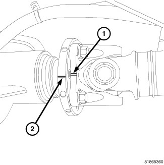
Mark an installation reference line across the front propeller shaft flange (1) and the axle flange (2).
-
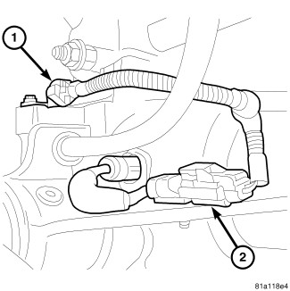
Disconnect Tru-Lok wiring connectors (1,2) and axle vent hose.

- Remove brake calipers and rotors.
- Remove wheel speed sensors (1) from hub bearings.
-
Remove brake lines and sensor wiring from axle.
-
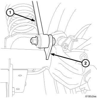
Remove stabilizer bar links (1) from axle brackets (2).
-
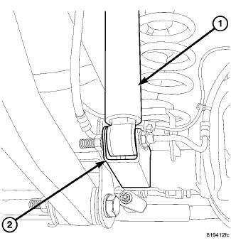
Remove shock absorbers (1) from axle brackets (2).
-
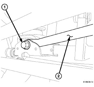
Remove track bar bolt (1) and track bar (2) from axle bracket.
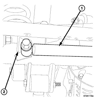
-
Remove steering damper (1) from axle bracket (2).
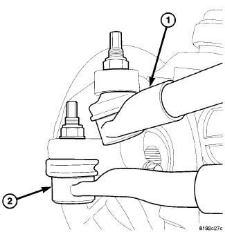
-
Remove drag link (1) and tie rod ends (2) from steering knuckles.
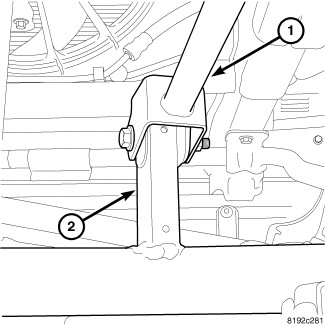
-
Remove upper control arms (1) from axle brackets (2).
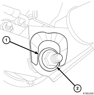
- Mark lower control arm cams (1) for installation reference and loosen nuts (2).
- Lower axle enough to remove coil springs from axle.
-
Remove lower control arm bolts remove axle from vehicle.
INSTALLATION
INSTALLATION
 |
The weight of the vehicle must
be supported by the springs before suspension arms and track bar fasteners
can be tightened. Failure to follow these instruction will result
in damaging the bushings.
CAUTION:
| NOTE: |
Procedure is the same for a 4x2 tube axle except for propeller shaft and axle vent installation. |
- Position axle under vehicle.
- Install lower control arms in axle brackets.
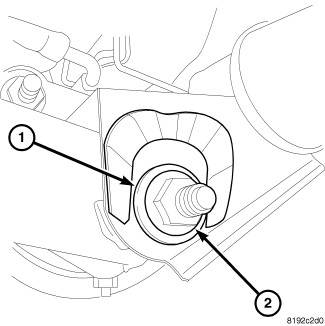
- Install lower control arm bolts, cams (1) and loosely install nuts (2).
-
Install coil springs on axle and raise axle into position.
-
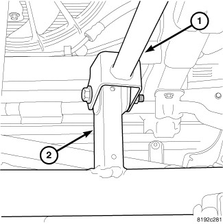
Install upper control arms (1) on axle brackets (2) and loosely install bolts and nuts.
-
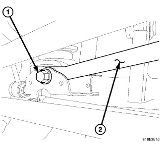
Install track bar (2) in axle bracket and loosely install bolt (1).
-
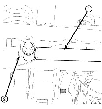
Install steering damper (1) on axle bracket (2) and tighten to specification.
-
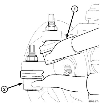
Install drag link (1) and (2) tie rod ends on steering knuckles and tighten to specification.
-
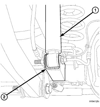
Install shock absorbers (1) on axle brackets (2) and tighten to specification.
-
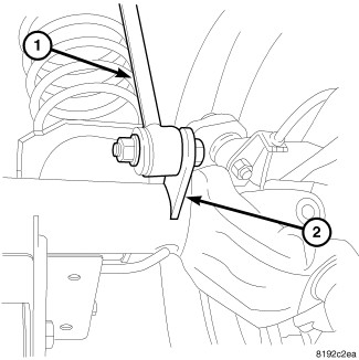
Install stabilizer bar links (1) on axle brackets (2) and tighten to specification.
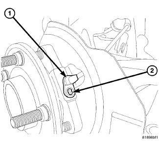
- Install wheel speed sensors harness on axle and install sensors (1) in hub bearings.
-
Install brake rotors, calipers and brakes lines.
-
Connect Tru-Lok wiring connectors (1,2) and axle vent hose.
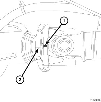
NOTE: Clean all propeller shaft bolts and apply Mopar® Lock AND Seal Adhesive or equivalent to the threads before installation.
-
Install propeller shaft with axle flange (2) and propeller shaft (1) marks aligned.
- Remove lift from the axle.
- Install wheel and lower vehicle.
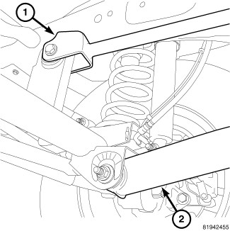
- Align lower control arm (2) cams to reference marks and tighten control arm nuts to specification.
-
Tighten upper (1) control arm nuts to specification.
-
Tighten track bar (2) bolt (1) at axle bracket to torque specification.
SPECIAL TOOLS
SPECIAL TOOLS
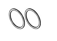 |
10178 - Shims, Dummy Originally Shipped In Kit Number(s) 10178. |
 |
6739 - Block, Height Originally Shipped In Kit Number(s) 6730, 9516A-CAN, 9540, 9541. |
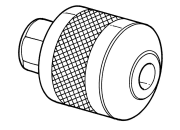 |
6740 - Cone Originally Shipped In Kit Number(s) 6730, 6731, 9516A-CAN, 9540, 9541. |
 |
6741 - Screw Originally Shipped In Kit Number(s) 6730, 6731, 9516A-CAN, 9540, 9541. |
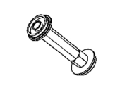 |
6764 - Installer, Axle Seal |
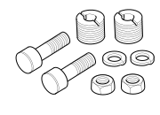 |
6987B - Adapter Kit, Axle Spreader Originally Shipped In Kit Number(s) 6980, 6994, 6995, 8653. |
 |
8109 - Cup Originally Shipped In Kit Number(s) 8163, 8163CC, 8164, 8164CC, 8165, 8165CC. |
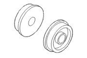 |
8110 - Installer, Seal Originally Shipped In Kit Number(s) 8163, 8163CC, 8165, 8165CC. |
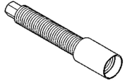 |
8112 - Screw Originally Shipped In Kit Number(s) 8163, 8163CC, 8164, 8164CC, 8165, 8165CC. |
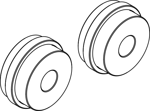 |
8541A - Set, Arbor Disc Originally Shipped In Kit Number(s) 8555, 9975. |
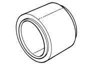 |
8681 - Installer, Seal Originally Shipped In Kit Number(s) 8696, 8696CC, 8710, 8710CC, 9988, 9989. |
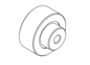 |
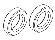
9990 - Gauge, Pinion Height Originally Shipped In Kit Number(s) 9945-SUP. |
 |
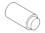
9992 - Bearings, Dummy Originally Shipped In Kit Number(s) 9945-SUP. |
 |
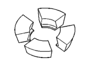
C-293-3 - Adapter, Bearing/Gear Originally Shipped In Kit Number(s) 8418, 8837, C-293-M, C-4246-AL, DD-914-CLT-L. |
 |
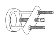
C-293-47 - Block Set, Puller Originally Shipped In Kit Number(s) 9975, C-293-M, DD-914-CLT-L. |
 |
C-293-PA - Puller, Press Originally Shipped In Kit Number(s) 8418, 8837, C-293-M. |
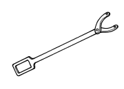 |
C-3281 - Holder, Flange Originally Shipped In Kit Number(s) 9202, 9202A-CAN, 9202CC, 9299, 9299CC, 9299CC, 9300A-CAN. |
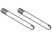 |
C-3288-B - Set, Alignment Pins Originally Shipped In Kit Number(s) 9975. |
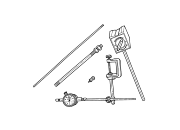 |
C-3339A - Set, Dial Indicator Originally Shipped In Kit Number(s) 9202. |
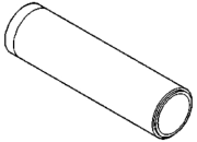 |
C-4040 - Installer, Bearing Originally Shipped In Kit Number(s) 9398. |
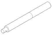 |
C-4171 - Driver Handle, Universal Originally Shipped In Kit Number(s) 9202, 9202A-CAN, 9202CC, 9299, 9299CC, 9299CC, 9300A-CAN. |
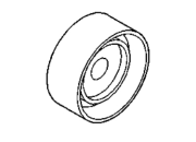 |
C-4213 - Installer, Bearing Originally Shipped In Kit Number(s) 9685, 9695, 9720-SUP, 9945-SUP2, 9995. |
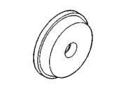 |
C-4308 - Installer, Bearing Cup Originally Shipped In Kit Number(s) 9695. |
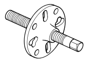 |
C-452 - Puller, Companion Flange |
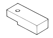 |
D-115-2A - Block, Scooter Originally Shipped In Kit Number(s) 9329-SUP, 9515-SUP, 9516-SUP, 9517-SUP, 9518, 9519, 9540-SUP, 9541-SUP, 9694, 9926. |
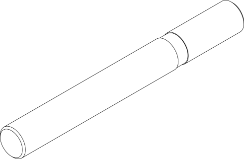 |
D-115-3 - Arbor Originally Shipped In Kit Number(s) 8667, 9516A-CAN. |
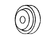 |
D-146 - Installer, Bearing Cup Originally Shipped In Kit Number(s) 8667. |
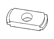 |
D-158 - Remover, Bearing Cup Originally Shipped In Kit Number(s) 6745, 9945-SUP3. |
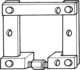 |
W-129-B - Spreader, Differential Originally Shipped In Kit Number(s) 9975. |