07 - Cooling
- DESCRIPTION
- OPERATION
- PRELIMINARY CHECKS
- LEAK TESTING
- CLEANING/REVERSE FLUSHING
- DRAINING - GAS
- DRAINING - DIESEL
- STANDARD PROCEDURE - COOLANT AIR EVACUATION
- LEVEL CHECK
- TORQUE
- COOLANT FILL VOLUMES
- SPECIAL TOOLS
DESCRIPTION
DESCRIPTION
The cooling system regulates engine operating temperature. It allows the engine to reach normal operating temperature as quickly as possible, maintains normal operating temperature and prevents overheating.
The cooling system also provides a means of heating the passenger compartment and cooling the automatic transmission fluid. The cooling system is pressurized and uses a centrifugal water pump to circulate coolant throughout the system.
COOLING SYSTEM COMPONENTS
The cooling system consists of:
OPERATION
OPERATION
- When engine is cold the thermostat is closed. The cooling system has no flow through the radiator. The coolant flows through the engine, water pump, and heater.
- When engine is warm, the thermostat is full open. The coolant flows through the engine, radiator, heater, and water pump.
- On the diesel engine coolant flows through the engine, radiator, heater, and water pump.
- As coolant expands, some coolant will move to the coolant recovery container. Once the coolant cools, the coolant from the coolant recovery container will move back to the radiator. (Gas engine only)
PRELIMINARY CHECKS
PRELIMINARY CHECKS
ENGINE COOLING SYSTEM OVERHEATING
Establish what driving conditions caused the complaint. Abnormal loads on the cooling system such as the following may be the cause:
- Prolonged idle
- Very high ambient temperature
- Overloaded Truck
- Slow traffic
- Traffic jams
- High speed or steep grades
- Snow Plow restricting airflow through cooling module
- Debris on front of the grill or the cooling module that is restricting airflow
Driving techniques that avoid overheating are:
- Idle with A/C off when temperature gauge is at end of normal range.
- Increasing engine speed up to 2000 rpm with transmission in park or neutral for more airflow is recommended.
- If equipped with a snow plow. Activate the snow plow mode.
TRAILER TOWING:
Consult Trailer Towing section of the owners manual. Do not exceed the limits.
RECENT SERVICE OR ACCIDENT REPAIR:
Determine if any recent service has been performed on vehicle that may affect the cooling system. This may be:
- Engine adjustments (incorrect timing)
- Slipping engine accessory drive belt(s)
- Brakes (possibly dragging)
- Changed parts. Incorrect water pump or pump rotating in wrong direction due to belt not correctly routed
- Reconditioned radiator or cooling system refilling (possibly under filled or air trapped in system).
- Service to electrically controlled viscous fan clutch
| NOTE: |
If investigation reveals none of the previous items as a cause for an engine overheating complaint, refer to the COOLING SYSTEM DIAGNOSIS CHART. |
These charts are to be used as a quick-reference only.
COOLING SYSTEM DIAGNOSIS CHART
|
CONDITION |
POSSIBLE CAUSES |
CORRECTION |
||||
|---|---|---|---|---|---|---|
|
TEMPERATURE GAUGE READS LOW
|
1. Vehicle is equipped with a heavy duty cooling system. |
1. None. System operating normally. |
||||
|
2. Thermostat stuck open |
2. Inspect and test thermostat (Refer to 07 - Cooling/Engine/THERMOSTAT - Diagnosis and Testing) . |
|||||
|
3. Coolant level low. |
3. Fill cooling system (Refer to 07 - Cooling - Standard Procedure) . |
|||||
|
4. Temperature gauge not functioning correctly. |
4. Check cluster (Refer to 08 - Electrical/8J - Instrument Cluster - Diagnosis and Testing) . |
|||||
|
5. Engine sensor stuck in range |
5. Monitor sensor with scan tool to verify sensor reading changes with increasing temperature. |
|||||
|
6. Engine sensor failed out of range. |
6. A DTC will be set. |
|||||
|
7. Electronically Controlled Viscous Fan Drive/mechanical viscous fan not operating properly. |
7. Check Electronically Controlled Viscous Fan Drive . |
|||||
|
TEMPERATURE GAUGE READS HIGH. COOLANT MAY OR MAY NOT BE LEAKING FROM SYSTEM
|
1. Vehicle overloaded, high ambient (outside) temperatures with A/C turned on, stop and go driving or prolonged operation at idle speeds. |
1. Temporary condition, repair not required. Notify customer of vehicle operation instructions located in Owners Manual. |
||||
|
2. Electronically-controlled viscous fan clutch not functioning correctly. |
2. Troubleshoot and if necessary repair the electronic viscous fan clutch. |
|||||
|
3. Temperature gauge not functioning correctly. |
3. Check cluster (Refer to 08 - Electrical/8J - Instrument Cluster - Diagnosis and Testing) . |
|||||
|
4. Air trapped in cooling system |
4. Drain and refill cooling system (Refer to 07 - Cooling - Standard Procedure) . |
|||||
|
5. Radiator cap faulty. |
5. Replace radiator cap. |
|||||
|
6. Plugged A/C or radiator cooling fins. |
6. Clean all debris away from A/C and radiator cooling fins. |
|||||
|
7. Coolant mixture incorrect. |
7. Drain cooling system and refill with correct mixture (Refer to 07 - Cooling - Standard Procedure) . |
|||||
|
8. Thermostat stuck shut. |
8. Inspect and test thermostat (Refer to 07 - Cooling/Engine/THERMOSTAT - Diagnosis and Testing) |
|||||
|
9. Bug screen or winter front being used. |
9. Remove bug screen or winter front. |
|||||
|
10. Electronically controlled viscous fan drive not operating properly. |
10. Check viscous fan . |
|||||
|
11. Cylinder head gasket leaking. |
11. Check for leaking head gaskets (Refer to 07 - Cooling - Diagnosis and Testing) . |
|||||
|
12. Heater core leaking. |
12. Replace heater core (Refer to 24 - Heating and Air Conditioning/Plumbing/CORE, Heater - Removal) . |
|||||
|
13. Cooling system hoses leaking. |
13. Tighten clamps or Replace hoses. |
|||||
|
14. Brakes dragging. |
14. Check brakes (Refer to 05 - Brakes - Diagnosis and Testing) . |
|||||
|
15. Accessory drive belt. |
15. Inspect and replace as necessary (Refer to 07 - Cooling/Accessory Drive/BELT, Serpentine - Diagnosis and Testing) . |
|||||
|
16. Water Pump. |
16. Inspect and replace as necessary . |
|||||
|
17. Engine sensor stuck in range. |
17. Monitor sensor with scan tool to verify sensor reading changes increase in temperature. |
|||||
|
18. Temperature sensor failed - Too High |
18. Clear the existing overheat fault. Drive the vehicle until thermostat opens. Verify that fault code does not return and coolant does not reach threshold of 230 degrees F. |
|||||
|
TEMPERATURE GAUGE READING INCONSISTENT (ERRATIC, CYCLES OR FLUCTUATES)
|
1. Heavy duty cooling system, extreme cold ambient (outside) temperature or heater blower motor in high position. |
1. None. System operating normally. |
||||
|
2. Temperature gauge or sensor defective. |
2. Check cluster or engine coolant temp sensor (Refer to 08 - Electrical/8J - Instrument Cluster - Diagnosis and Testing) . |
|||||
|
3. Temporary heavy usage or load. |
3. None. Normal condition. |
|||||
|
4. Air trapped in cooling system. |
4. Fill cooling system (Refer to 07 - Cooling - Standard Procedure) . |
|||||
|
5. Water pump. |
5. Replace water pump . |
|||||
|
6. Air leak on suction side of water pump. |
6. Check for leak (Refer to 07 - Cooling - Diagnosis and Testing) . |
|||||
|
RADIATOR CAP LEAKING STEAM AND OR COOLANT INTO RESERVOIR BOTTLE. (TEMPERATURE GAUGE MAY READ HIGH) |
1. Radiator cap defective. |
1. Replace radiator cap. |
||||
|
2. Radiator neck surface damaged. |
2. Replace radiator (Refer to 07 - Cooling/Engine/RADIATOR, Engine Cooling - Installation) . |
|||||
|
HOSE OR HOSES COLLAPSE WHEN ENGINE IS COOLING. |
1. Vacuum created in cooling system on engine cool-down is not being relieved through coolant reservoir/overflow system. |
1. Replace radiator cap, check vent hose between radiator and reservoir bottle for blockage also check reservoir bottle vent for blockage. |
||||
|
NOISY FAN |
1. Fan blade(s) loose, damaged. |
1. Replace fan blade assembly. |
||||
|
2. Electronically controlled viscous fan drive/mechanical viscous fan. |
2. None. Normal condition. |
|||||
|
3. Fan blades striking surrounding objects. |
3. Locate contact point and repair as necessary. |
|||||
|
4. Electronically controlled viscous fan drive/mechanical viscous fan bearing concern. |
4. Check viscous fan drive. |
|||||
|
5. Electronically controlled viscous fan/mechanical viscous fan stuck on. |
5. Check viscous fan drive. |
|||||
|
6. Obstructed air flow through radiator. |
6. Remove obstruction. |
|||||
|
INADEQUATE AIR CONDITIONER PERFORMANCE (COOLING SYSTEM SUSPECTED) |
1. Radiator and/or A/C condenser air flow obstructed. |
1. Remove obstruction and/or clean. |
||||
|
2. Electronically controlled viscous fan drive/ /mechanical viscous fan not working. |
2. Check viscous fan drive. |
|||||
|
3. Air seals around radiator damaged or missing. |
3. Inspect air seals, repair or replace as necessary. |
|||||
|
INADEQUATE HEATER PERFORMANCE. GAUGE MAY OR MAY NOT READ LOW. |
1. Heavy duty cooling system, and cooler ambient temperatures. |
1. None. Normal condition. |
||||
|
2. Obstruction in heater hoses. |
2. Remove hoses, remove obstruction. |
|||||
|
3. Electronically controlled viscous fan/ /mechanical viscous fan stuck on. |
Check viscous fan drive. |
|||||
|
4. Water pump damaged. |
4. Replace water pump. |
|||||
|
HEAT ODOR |
1. Damaged or missing exhaust system heat shields. |
1. Repair or replace damaged or missing exhaust system heat shields (Refer to 11 - Exhaust System/SHIELD, Heat - Description) . |
||||
|
2. Electronically controlled viscous fan drive//mechanical viscous fan damaged. |
2. Check viscous fan drive. |
LEAK TESTING
LEAK TESTING
ULTRAVIOLET LIGHT METHOD
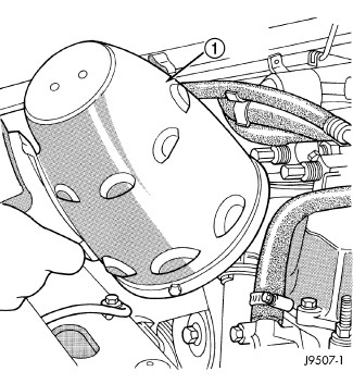 |
All Jeep models have a leak detection additive added to the cooling system before they leave the factory. The additive is highly visible under ultraviolet light (black light). If the factory original coolant has been drained, pour one ounce of additive into the cooling system. The additive is available through the parts department. Place the heater control unit in HEAT position. Start and operate the engine until the radiator upper hose is warm to the touch. Aim the commercially available black light tool at the components to be checked. If leaks are present, the black light will cause the additive to glow a bright green color.
The black light can be used along with a pressure tester to determine if any external leaks exist.
PRESSURE TESTER METHOD
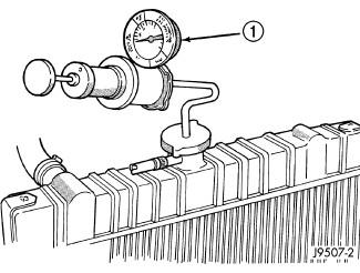 |
The engine should be at the normal operating temperature. Recheck the system cold if the cause of coolant loss is not located during warm engine examination.
Hot, pressurized coolant can cause injury by scalding.
WARNING:
Carefully remove the radiator pressure cap from the filler neck and check the coolant level. Push down on the cap to disengage it from the stop tabs. Wipe the inner part of the filler neck and examine the lower inside sealing seat for nicks, cracks, paint, dirt and solder residue. Inspect the reserve/overflow tank tube for internal obstructions. Insert a wire through the tube to be sure it is not obstructed.
Inspect the cams on the outside part of the filler neck. If the cams are bent, seating of pressure cap valve and tester seal will be affected. Replace cap if cams are bent.
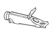
Attach pressure tester 7700 (or an equivalent) to the radiator filler neck.
Operate the tester pump to apply 124 kPa (18 psi) pressure to the system. If the hoses enlarge excessively or bulge while testing, replace as necessary. Observe the gauge pointer and determine the condition of the cooling system according to the following criteria:
- Holds Steady: If the pointer remains steady for two minutes, there are no serious coolant leaks in the system. However, there could be an internal leak that does not appear with normal system test pressure. Inspect for interior leakage or do the Internal Leakage Test. Do this if it is certain that coolant is being lost and no leaks can be detected.
- Drops Slowly: Shows a small leak or seepage is occurring. Examine all connections for seepage or slight leakage with a flashlight. Inspect the radiator, hoses, gasket edges and heater. Seal any small leak holes with a Sealer Lubricant or equivalent. Repair leak holes and reinspect the system with pressure applied.
-
Drops Quickly: Shows that a serious leakage is occurring. Examine the system for serious external leakage. If no leaks are visible, inspect for internal leakage. Large radiator leak holes should be repaired by a reputable radiator repair shop.
INTERNAL LEAKAGE INSPECTION
Remove the engine oil pan drain plug and drain a small amount of engine oil. Coolant, being heavier than engine oil, will drain first. Another way of testing is to operate the engine and check for water globules on the engine oil dipstick. Also inspect the automatic transmission oil dipstick for water globules. Inspect the automatic transmission fluid cooler for leakage. Operate the engine without the pressure cap on the radiator until thermostat opens.
Attach a pressure tester to the filler neck. If pressure builds up quickly, a leak exists as a result of a faulty cylinder head gasket or crack in the engine. Repair as necessary.
DO NOT ALLOW PRESSURE TO EXCEED 124 KPA (18 PSI). TURN THE ENGINE OFF. TO RELEASE THE PRESSURE, ROCK THE TESTER FROM SIDE TO SIDE. WHEN REMOVING THE TESTER, DO NOT TURN THE TESTER MORE THAN 1/2 TURN IF THE SYSTEM IS UNDER PRESSURE.
WARNING:
If there is no immediate pressure increase, pump the pressure tester until the indicated pressure is within the system range. Vibration of the gauge pointer indicates compression or combustion leakage into the cooling system.
Do not disconnect the spark plug wires while the engine is operating.
WARNING:
Do not operate the engine with
a spark plug shorted for more than a minute. The catalytic converter
may be damaged.
CAUTION:
Isolate the compression leak by shorting each spark plug to the cylinder block. The gauge pointer should stop or decrease vibration when spark plug for leaking cylinder is shorted. This happens because of the absence of combustion pressure.
COMBUSTION LEAKAGE TEST (WITHOUT PRESSURE TESTER)
DO NOT WASTE reusable coolant. If the solution is clean, drain the coolant into a clean container for reuse.
Do not remove the cylinder block drain plugs or loosen the radiator draincock with the system hot and under pressure. Serious burns from coolant can occur.
WARNING:
Remove thermostat (Refer to 07 - Cooling/Engine/THERMOSTAT - Removal) .
Remove accessory drive belt (Refer to 07 - Cooling/Accessory Drive/BELT, Serpentine - Removal) .
Add coolant to the radiator to bring the level to within 6.3 mm (1/4 in) of the top of the thermostat housing.
Avoid overheating. Do not operate
the engine for an excessive period of time. Open the draincock immediately
after the test to eliminate boil over of coolant.
CAUTION:
Start the engine and accelerate rapidly three times (to approximately 3000 rpm) while observing the coolant. If internal engine combustion gases are leaking into the cooling system, bubbles will appear in the coolant. If bubbles do not appear, there is no internal combustion gas leakage.
CLEANING/REVERSE FLUSHING
CLEANING/REVERSE FLUSHING
The cooling system normally operates
at 97 - 110 kPa (14 -16 psi) pressure. Exceeding this pressure may
damage the radiator or hoses.
CAUTION:
Reverse flushing of the cooling system is the forcing of water through the cooling system. This is done using air pressure in the opposite direction of normal coolant flow. It is usually only necessary with very dirty systems with evidence of partial plugging.
CHEMICAL CLEANING
If visual inspection indicates the formation of sludge or scaly deposits, use a radiator cleaner, Mopar® Radiator Kleen or equivalent, before flushing. This will soften scale and other deposits and aid the flushing operation.
Be sure instructions on the container
are followed.
CAUTION:
REVERSE FLUSHING RADIATOR
Disconnect the radiator hoses from the radiator fittings. Attach a section of radiator hose to the radiator bottom outlet fitting and insert the flushing gun. Connect a water supply hose and air supply hose to the flushing gun.
The cooling system normally operates
at 97 - 110 kPa (14 - 16 psi) pressure. Exceeding this pressure may
damage the radiator or hoses.
CAUTION:
Allow the radiator to fill with water. When radiator is filled, apply air in short blasts allowing radiator to refill between blasts. Continue this reverse flushing until clean water flows out through rear of radiator cooling tube passages. For more information, refer to operating instructions supplied with flushing equipment. Have radiator cleaned more extensively by a radiator repair shop.
REVERSE FLUSHING ENGINE
Drain the cooling system (Refer to 07 - Cooling - Standard Procedure) . Remove the thermostat housing and thermostat. Install the thermostat housing. Disconnect the radiator upper hose from the radiator and attach the flushing gun to the hose. Disconnect the radiator lower hose from the water pump. Attach a lead away hose to the water pump inlet fitting.
Be sure that the heater control
valve is closed (heat off). This is done to prevent coolant flow with
scale and other deposits from entering the heater core.
CAUTION:
Connect the water supply hose and air supply hose to the flushing gun. Allow the engine to fill with water. When the engine is filled, apply air in short blasts, allowing the system to fill between air blasts. Continue until clean water flows through the lead away hose. For more information, refer to operating instructions supplied with flushing equipment.
Remove the lead away hose, flushing gun, water supply hose and air supply hose. Remove the thermostat housing (Refer to 07 - Cooling/Engine/THERMOSTAT - Removal) . Install the thermostat and housing with a replacement gasket (Refer to 07 - Cooling/Engine/THERMOSTAT - Installation) . Connect the radiator hoses. Refill the cooling system with the correct antifreeze/water mixture (Refer to 07 - Cooling - Standard Procedure) .
DRAINING - GAS
DRAINING - GAS
 |
Do not remove the cylinder block drain plugs or loosen the radiator draincock with system hot and under pressure. Serious burns from coolant can occur.
WARNING:
| NOTE: |
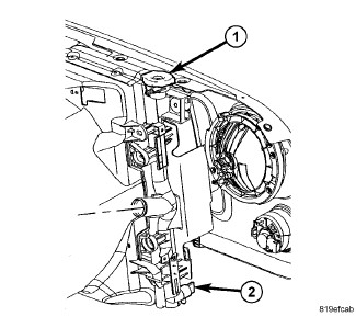
Radiator draincock is located on the right/lower side of radiator facing to front of vehicle. |
- Remove radiator pressure cap from radiator or coolant recovery container as necessary.
- Raise and support vehicle.
- Attach one end of a hose to the draincock. Put the other end into a clean container. Open draincock and drain coolant from radiator.
-
If necessary, siphon coolant from coolant recovery container. (Diesel engine)
DRAINING - DIESEL
DRAINING - DIESEL
 |
Do not remove the cylinder block drain plugs or loosen the radiator draincock with system hot and under pressure. Serious burns from coolant can occur.
WARNING:
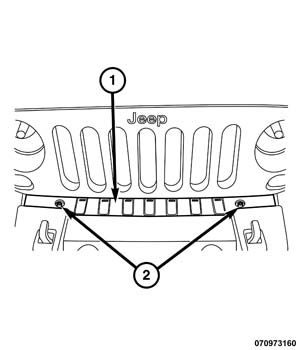
DO NOT remove the radiator cap when draining the coolant from the reserve/overflow tank. Open the radiator draincock and when the tank is empty, remove the radiator cap. The coolant does not have to be removed from the tank unless the system is being refilled with a fresh mixture.
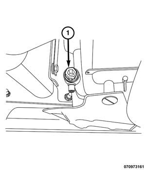
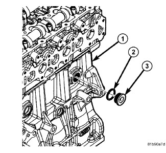
STANDARD PROCEDURE - COOLANT AIR EVACUATION
STANDARD PROCEDURE - COOLANT AIR EVACUATION
 |
Evacuating or purging air from the cooling system involves the use of a pressurized air operated vacuum generator. The vacuum created allows for a quick and complete coolant refilling while removing any airlocks present in the system components.
| NOTE: |
To avoid damage to the cooling system, ensure that no component would be susceptible to damage when a vacuum is drawn on the system. |
ANTIFREEZE IS AN ETHYLENE GLYCOL BASE COOLANT AND IS HARMFUL IF SWALLOWED OR INHALED. IF SWALLOWED, DRINK TWO GLASSES OF WATER AND INDUCE VOMITING. IF INHALED, MOVE TO FRESH AIR AREA. SEEK MEDICAL ATTENTION IMMEDIATELY. DO NOT STORE IN OPEN OR UNMARKED CONTAINERS. WASH SKIN AND CLOTHING THOROUGHLY AFTER COMING IN CONTACT WITH ETHYLENE GLYCOL. KEEP OUT OF REACH OF CHILDREN. DISPOSE OF GLYCOL BASED COOLANT PROPERLY. CONTACT YOUR DEALER OR GOVERNMENT AGENCY FOR LOCATION OF COLLECTION CENTER IN YOUR AREA. DO NOT OPEN A COOLING SYSTEM WHEN THE ENGINE IS AT OPERATING TEMPERATURE OR HOT UNDER PRESSURE; PERSONAL INJURY CAN RESULT. AVOID RADIATOR COOLING FAN WHEN ENGINE COMPARTMENT RELATED SERVICE IS PERFORMED; PERSONAL INJURY CAN RESULT.
WARNING:
WEAR APPROPRIATE EYE AND HAND PROTECTION WHEN PERFORMING THIS PROCEDURE.
WARNING:
| NOTE: |
The service area where this procedure is performed should have a minimum shop air requirement of 80 PSI (5.5 bar) and should be equipped with an air dryer system. |
| NOTE: |
For best results, the radiator should be empty. The vehicle's heater control should be set to the heat position (ignition may need to be turned to the on position but do not start the motor). |
- Refer to the Chrysler Pentastar Service Equipment (Chrysler PSE) Coolant Refiller #85-15-0650 or equivalent tool's operating manual for specific assembly steps.
- Choose an appropriate adapter cone that will fit the vehicle's radiator filler neck or reservoir tank.
-
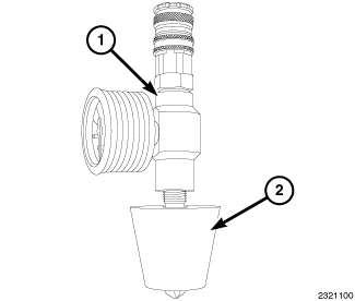
Attach the adapter
cone (2) to the vacuum gauge (1).
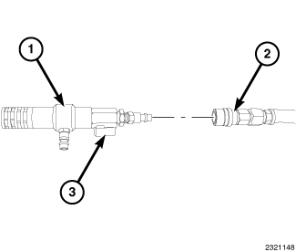
- Make sure the vacuum generator/venturi ball valve (3) is closed and attach an airline hose (2) (minimum shop air requirement of 80 PSI/5.5 bar) to the vacuum generator/venturi (1).
-
Position the adaptor
cone/vacuum gauge assembly into the radiator filler neck or reservoir
tank. Ensure that the adapter cone is sealed properly.
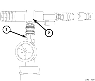
- Connect the vacuum generator/venturi (2) to the positioned adaptor cone/vacuum gauge assembly (1).
-
Open the vacuum generator/venturi
ball valve.
NOTE: Do not bump or move the assembly as it may result in loss of vacuum. Some radiator overflow hoses may need to be clamped off to obtain vacuum.
-
Let the system run
until the vacuum gauge shows a good vacuum through the cooling system.
Refer to the tool's operating manual for appropriate pressure readings.
NOTE: If a strong vacuum is being created in the system, it is normal to see the radiator hoses to collapse.
-
Close the vacuum generator/venturi
ball valve.
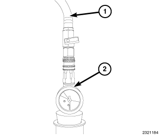
- Disconnect the vacuum generator/venturi and airline from the adaptor cone/vacuum gauge assembly.
- Wait approximately 20 seconds, if the pressure readings do not move, the system has no leaks. If the pressure readings move, a leak could be present in the system and the cooling system should be checked for leaks and the procedure should be repeated.
-
Place the tool's suction
hose into the coolant's container.
NOTE: Ensure there is a sufficient amount of coolant, mixed to the required strength/protection level available for use. For best results and to assist the refilling procedure, place the coolant container at the same height as the radiator filler neck. Always draw more coolant than required. If the coolant level is too low, it will pull air into the cooling system which could result in airlocks in the system.
-
Connect the tool's
suction hose (1) to the adaptor cone/vacuum gauge assembly (2).
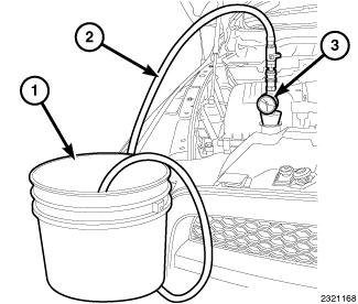
NOTE: View typical - Open the suction hose's ball valve to begin refilling the cooling system.
-
When the vacuum gauge
reads zero, the system is filled.
NOTE: On some remote pressurized tanks, it is recommended to stop filling when the proper level is reached.
- Close the suction hose's ball valve and remove the suction hose from the adaptor cone/vacuum gauge assembly.
- Remove the adaptor cone/vacuum gauge assembly from the radiator filler neck or reservoir tank.
- With heater control unit in the HEAT position, operate engine with container cap in place.
- After engine has reached normal operating temperature, shut engine off and allow it to cool. When engine is cooling down, coolant will be drawn into the radiator from the pressure container.
- Add coolant to the recovery bottle/container as necessary. Only add coolant to the container when the engine is cold. Coolant level in a warm engine will be higher due to thermal expansion. Add necessary coolant to raise container level to the COLD MINIMUM mark after each cool down period.
-
Once the appropriate
coolant level is achieved, attach the radiator cap or reservoir tank
cap.
LEVEL CHECK
LEVEL CHECK
| NOTE: |
Do not remove radiator cap for routine coolant level inspections. The coolant level can be checked at coolant reserve/overflow tank. |
The coolant reserve/overflow system provides a quick visual method for determining coolant level without removing radiator pressure cap. With engine idling and at normal operating temperature, observe coolant level in reserve/overflow tank. The coolant level should be between ADD and FULL marks.
TORQUE
TORQUE
|
DESCRIPTION |
N·m |
Ft. Lbs. |
In. Lbs. |
|---|---|---|---|
|
Bolt, Accessory Drive Belt Tensioner (3.6L) |
33 |
24 |
- |
|
Bolts, Accessory Drive Belt Hydraulic Tensioner (3.6L) |
22.5 |
16.6 |
- |
|
Bolt, Accessory Drive Belt Tensioner (2.8L) |
55 |
40 |
- |
|
Bolt, Block Heater |
12 |
- |
106 |
|
Bolts, Condenser to Radiator |
8 |
18 |
70 |
|
Bolts, EGR Cooler |
15 |
- |
133 |
|
Bolt, EGR Cooler Manifold Elbow |
11 |
- |
97 |
|
Bolts, EGR Cooler Manifold Support Bracket |
45 |
33 |
- |
|
Bolts, EGR Cooler Support Bracket |
25 |
18 |
- |
|
Bolts, Fan Shroud to Radiator Mounting |
4.5 |
- |
40 |
|
Bolt, Idler Pulley |
|||
|
2.8L |
45 |
33 |
- |
|
3.6L |
25 |
18 |
- |
|
Bolts, Radiator Upper Isolator to Crossmember |
8 |
- |
70 |
|
Bolts, Thermostat Housing |
12 |
- |
106 |
|
Bolts, Water Pump |
|||
|
2.8L |
32 |
24 |
- |
|
3.6L |
|||
|
M6 |
12 |
9 |
106 |
|
M8 |
23 |
17 |
- |
|
M10 |
50 |
37 |
- |
|
Electric Fan to Fan Shroud Bolts |
8 |
- |
70 |
|
Nuts, Coolant Recovery Bottle |
10 |
- |
89 |
|
Nuts, EGR Cooler Manifold |
25 |
18 |
- |
|
Viscous Fan Drive - Diesel |
50 |
37 |
- |
COOLANT FILL VOLUMES
COOLANT FILL VOLUMES
|
DESCRIPTION |
SPECIFICATION |
|
|---|---|---|
|
Metric |
US |
|
|
2.8L DIESEL |
12 L |
13 qts |
|
3.6L |
10.8 L |
11.4 qts. |
SPECIAL TOOLS
SPECIAL TOOLS
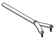 |
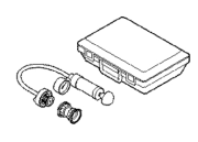
6958 - Wrench, Spanner Originally Shipped In Kit Number(s) 6947, 6949, 6966, 8204, 8204CC, 8667. |
 |
7700 - Tester, Cooling System Originally Shipped In Kit Number(s) 7700-A. |
 |
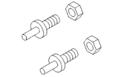
8286 - Refractometer |
 |
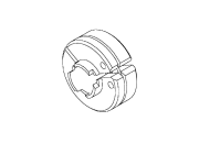
8346 - Pins, Adapter Originally Shipped In Kit Number(s) 8503, 8510, 8520, 8520CC. |
 |
8875A - Disconnect, Transmission Cooler Line Originally Shipped In Kit Number(s) 9202, 9328, 9328-CAN, 9329, 9516, 9575. |