8R - Wipers/Washers
FRONT
FRONT
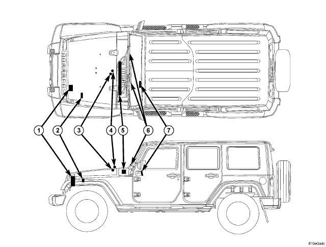 |
An electrically operated intermittent front wiper and washer system is standard factory-installed safety equipment on this vehicle. The wiper and washer system includes the following major components, which are described in further detail elsewhere in this service information:
- ElectroMechanical Instrument Cluster - The ElectroMechanical Instrument Cluster (EMIC) (also known as the Cab Compartment Node/CCN) is located on the instrument panel directly in front of the driver. (Refer to 08 - Electrical/8J - Instrument Cluster - Description) .
- Front Washer Check Valve (3) - A check valve is located in the front washer plumbing on the underside of the hood panel near the front washer nozzle.
- Front Washer Nozzle (4) - A single fluidic front washer nozzle is secured by an integral latch feature to a dedicated opening in the center of the hood panel near the base of the windshield.
- Front Washer Plumbing - The plumbing for the washer system consists of rubber hoses and molded rubber or plastic fittings. The plumbing is routed from the washer reservoir along the left side of the engine compartment to the dash panel, then across the underside of the inner hood panel reinforcement to the washer nozzle.
- Front Wiper Arms And Blades (6) - The two front wiper arms are secured with nuts to the threaded ends of the two wiper pivot shafts, which extend through the cowl plenum cover/grille panel located near the base of the windshield. The two equal length front wiper blades are each secured to their wiper arm with an integral latch, and are parked on the glass near the bottom of the windshield when the front wiper system is not in operation.
- Front Wiper Module (5) - The wiper pivot shafts are the only visible components of the front wiper module. The remainder of the module is concealed within the cowl plenum beneath the cowl plenum cover/grille panel. The wiper module includes the wiper module bracket, three rubber-isolated wiper module mounts, the wiper motor, the wiper motor crank arm, the two wiper drive links, the two wiper pivots and the two pivot water shields.
- Right Multi-Function Switch (7) - The right (wiper) multi-function switch and the left (lighting) multi-function switch are secured to brackets integral to the clockspring housing on the top of the steering column just below the steering wheel. The right multi-function switch is connected by a short jumper harness to the Steering Control Module (SCM), which is internal to the left multi-function switch housing. Only the switch control stalk extending from the right side of the steering column is visible, while the remainder of the switch is concealed beneath the steering column shrouds. The right multi-function switch is dedicated to providing all of the driver controls for both the front and rear wiper and washer systems.
- Steering Control Module - The Steering Control Module (SCM) is internal to the left multi-function switch housing, which is secured to a bracket integral to the left side of the clockspring housing on the top of the steering column just below the steering wheel. Only the left switch control stalk extending from the left side of the steering column is visible, while the remainder of the switch housing containing the SCM is concealed beneath the steering column shrouds. (Refer to 08 - Electrical/8E - Electronic Control Modules/MODULE, Steering Column - Description) .
- Totally Integrated Power Module (2) - The Totally Integrated Power Module (TIPM) is located in the engine compartment, near the battery. (Refer to 08 - Electrical/8W - Wiring/Power Distribution - Description) .
- Washer Pump/Motor - The single or reversible dual electric washer pump/motor unit is located in a dedicated hole in a sump area on the lower washer reservoir. The reversible dual washer pump/motor provides washer fluid to either the front or rear washer system plumbing, depending upon the direction of the pump motor rotation.
- Washer Reservoir (1) - The washer reservoir is located in the left front corner of the engine compartment. The reservoir filler cap is also accessed from the left front corner of the engine compartment.
Hard wired circuitry connects the front wiper and washer system components to the electrical system of the vehicle. These hard wired circuits are integral to several wire harnesses, which are routed throughout the vehicle and retained by many different methods. These circuits may be connected to each other, to the vehicle electrical system and to the front wiper and washer system components through the use of a combination of soldered splices, splice block connectors, and many different types of wire harness terminal connectors and insulators. Refer to the appropriate wiring information. The wiring information includes wiring diagrams, proper wire and connector repair procedures, further details on wire harness routing and retention, as well as pin out and location views for the various wire harness connectors, splices and grounds.
REAR
REAR
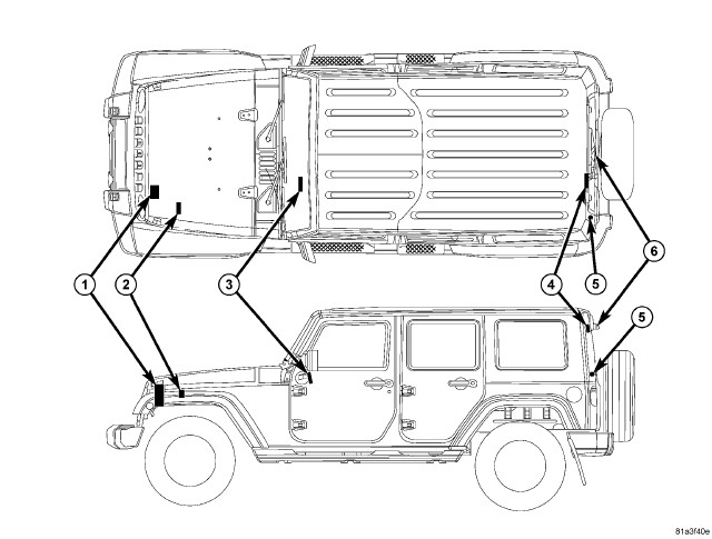 |
An electrically operated fixed interval intermittent rear wiper and washer system is standard factory-installed equipment on this vehicle when it is equipped with an optional hard top. The rear wiper and washer system includes the following major components, which are described in further detail elsewhere in this service information:
- ElectroMechanical Instrument Cluster - The ElectroMechanical Instrument Cluster (EMIC) (also known as the Cab Compartment Node/CCN) is located on the instrument panel directly in front of the driver. (Refer to 08 - Electrical/8J - Instrument Cluster - Description) .
- Rear Washer Check Valve (5) - A check valve is located in the hard top disconnect plate between the hard top washer supply hose and the body washer supply hose on the left inner D-pillar of the hard top.
- Rear Washer Nozzle - The fluidic rear washer nozzle is integral to the output shaft of the rear wiper motor on the left upper corner of the rear lift glass.
- Rear Washer Plumbing - The plumbing for the rear washer system consists of rubber hoses and molded plastic or rubber fittings. The plumbing is routed along the left side of the engine compartment from the washer reservoir, through the dash into the passenger compartment, down the left cowl side and sill to the body wire harness. The hose exits the body wire harness at the belt line of the left D-pillar where it connects through the rear check valve to a hard top hose that is routed up the D-pillar of the hard top to the upper lift glass opening header and then to the rear wiper motor.
- Rear Wiper Arm And Blade (6) - The single molded plastic rear wiper arm is secured by a nut directly to the rear wiper motor output shaft, which extends through a clearance hole near the upper left corner of the lift glass. The molded plastic rear wiper blade is secured by an integral pin to latches integral to the rear wiper arm, and is parked near the top of the lift glass when the rear wiper system is not in operation.
- Rear Wiper Motor (4) - The rear wiper motor includes the motor bracket and two rubber-isolated mounting tabs. The wiper motor output shaft is the only visible component of the rear wiper motor. The remainder of the motor is concealed by a molded plastic trim cover on the inner lift glass just below the lift glass opening header.
- Right Multi-Function Switch (3) - The right (wiper) multi-function switch and the left (lighting) multi-function switch are secured to brackets integral to the clockspring housing, on the top of the steering column just below the steering wheel. The right multi-function switch is connected by a short jumper harness to the Steering Control Module (SCM), which is internal to the left multi-function switch housing. Only the switch control stalk extending from the right side of the steering column is visible, while the remainder of the switch is concealed beneath the steering column shrouds. The right multi-function switch is dedicated to providing all of the driver controls for both the front and rear wiper and washer systems.
- Steering Control Module - The Steering Control Module (SCM) is internal to the left multi-function switch housing, which is secured to a bracket integral to the left side of the clockspring housing on the top of the steering column just below the steering wheel. Only the left switch control stalk extending from the left side of the steering column is visible, while the remainder of the switch housing containing the SCM is concealed beneath the steering column shrouds. (Refer to 08 - Electrical/8E - Electronic Control Modules/MODULE, Steering Column - Description) .
- Totally Integrated Power Module (2) - The Totally Integrated Power Module (TIPM) is located in the engine compartment, near the battery. (Refer to 08 - Electrical/8W - Wiring/Power Distribution - Description) .
- Washer Pump/Motor - The reversible dual electric washer pump/motor unit is located in a dedicated hole in a sump area on the lower washer reservoir. The dual washer pump/motor provides washer fluid to either the front or rear washer system plumbing, depending upon the direction of the pump motor rotation.
- Washer Reservoir (1) - The rear washer system shares a single reservoir and reversible pump with the front washer system, but has its own dedicated plumbing. The washer reservoir is located in the left front corner of the engine compartment. The filler cap is also accessed from the left front corner of the engine compartment.
Hard wired circuitry connects the rear wiper and washer system components to the electrical system of the vehicle. These hard wired circuits are integral to several wire harnesses, which are routed throughout the vehicle and retained by many different methods. These circuits may be connected to each other, to the vehicle electrical system and to the rear wiper and washer system components through the use of a combination of soldered splices, splice block connectors, and many different types of wire harness terminal connectors and insulators. Refer to the appropriate wiring information. The wiring information includes wiring diagrams, proper wire and connector repair procedures, further details on wire harness routing and retention, as well as pin out and location views for the various wire harness connectors, splices and grounds.
FRONT
FRONT
 |
The front wiper and washer system is designed to provide the vehicle
operator with a convenient, safe, and reliable means of maintaining
visibility through the windshield glass. The various components of
this system are designed to convert electrical energy produced by
the vehicle electrical system into the mechanical action of the wiper
blades to wipe the outside surface of the glass, as well as into the
hydraulic action of the washer system to apply washer fluid stored
in an on-board reservoir to the area of the glass to be wiped. When
combined, these components provide the means to effectively maintain
clear visibility for the vehicle operator by removing excess accumulations
of rain, snow, bugs, mud, or other minor debris from the outer surface
of the windshield glass that might be encountered while driving the
vehicle under numerous types of inclement operating conditions.
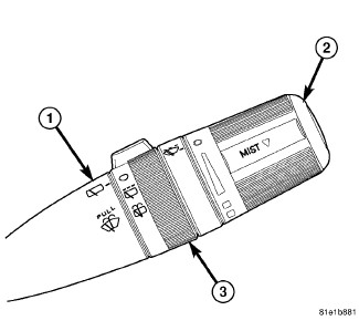
The vehicle operator initiates all front and rear wiper and washer system functions with the control stalk of the right (wiper) multi-function switch (1) that extends from the right side of the steering column, just below the steering wheel. Rotating the control knob (2) on the end of the control stalk, selects the OFF, DELAY, LOW, or HIGH front wiper system operating modes. In the DELAY mode, the control knob also allows the vehicle operator to select from one of five intermittent wipe delay intervals.
Pulling the control stalk rearward actuates the momentary front washer system switch, which selects the WASH and WIPE-AFTER-WASH modes, depending upon when and how long the switch is held closed. Pushing the control stalk downward actuates a momentary switch and selects the MIST mode, which cycles the wiper blades for as long as the switch is held closed then completes the current cycle and parks the blades at the base of the windshield after the switch is released.
The right multi-function switch provides hard wired analog and resistor multiplexed inputs to the Steering Control Module (SCM) internal to the left (lighting) multi-function switch housing for all of the wiper and washer system functions. The SCM then sends electronic wiper and washer switch status messages to the ElectroMechanical Instrument Cluster (EMIC) (also known as the Cab Compartment Node/CCN), over a Local Interface Network (LIN) data bus. The EMIC responds to the SCM inputs by sending electronic wiper and washer system request messages to the Totally Integrated Power Module (TIPM) over the Controller Area Network (CAN) data bus requesting the appropriate wiper and washer system operating modes.
Front wiper and washer system operation is completely controlled by the SCM, EMIC and TIPM logic circuits, and that logic will only allow these systems to operate when the ignition switch is in the ACCESSORY or ON positions. The TIPM uses intelligent, high current, self-protected high side switches to control wiper system operation by energizing or de-energizing the wiper motor low and high speed brushes. The TIPM uses an H-bridge circuit to control the operation of the reversible washer pump/motor unit. The right multi-function switch circuitry receives battery current and a clean ground output from the SCM, then provides analog and multiplexed inputs to the SCM to indicate the selected front wiper and front washer system mode.
The hard wired circuits and components of the front wiper and washer
system may be diagnosed using conventional diagnostic tools and procedures.
Refer to the appropriate wiring information. However, conventional
diagnostic methods will not prove conclusive in the diagnosis of the
front wiper and washer system or the electronic controls or communication
between other modules and devices that provide some features of the
front wiper and washer system. The most reliable, efficient, and accurate
means to diagnose the front wiper and washer system or the electronic
controls and communication related to front wiper and washer system
operation requires the use of a diagnostic scan tool. Refer to the
appropriate diagnostic information.
OPERATING MODES
Following are paragraphs that briefly describe the operation of each of the front wiper and washer system operating modes.
CONTINUOUS WIPE MODE
When the LOW position of the control knob on the control stalk of the right (wiper) multi-function switch is selected the SCM sends an electronic wiper switch low status message to the EMIC over the LIN data bus, the EMIC relays an electronic wiper switch low request message to the TIPM over the CAN data bus, then the TIPM directs battery current to the low speed brush of the wiper motor, causing the wipers to cycle at low speed.
When the HIGH position of the control knob is selected the SCM sends an electronic wiper switch high status message to the EMIC, the EMIC relays an electronic wiper switch high request message to the TIPM, then the TIPM directs battery current to the high speed brush of the wiper motor, causing the wipers to cycle at high speed.
When the OFF position of the multi-function switch control knob is selected, the SCM sends an electronic wiper switch off status message to the EMIC, the EMIC relays an electronic wiper switch off request message to the TIPM, then one of two events will occur. The event that occurs depends upon the position of the wiper blades on the windshield at the moment that the control knob OFF position is selected.
If the wiper blades are in the down position on the windshield when the OFF position is selected, the park switch that is integral to the wiper motor is closed to ground, which provides a hard wired park switch sense input to the TIPM. The TIPM then de-energizes the wiper motor and the wiper motor ceases to operate. If the wiper blades are not in the down position on the windshield at the moment the OFF position is selected, the park switch is an open circuit and the TIPM continues running the wiper motor at low speed until the wiper blades are in the down position on the windshield and the park switch input to the TIPM is again closed to ground.
INTERMITTENT WIPE MODE
When the control knob on the control stalk of the right (wiper) multi-function switch is moved to one of the five DELAY interval positions the SCM sends an electronic wiper switch delay interval status message to the EMIC, the EMIC relays an electronic wiper switch delay interval request message to the TIPM, then the TIPM electronic intermittent wipe logic circuit responds by calculating the correct length of time between wiper sweeps based upon the selected delay interval input.
The TIPM monitors the changing state of the wiper motor park switch through a hard wired park switch sense input. This input allows the TIPM to determine the proper intervals at which to energize and de-energize the wiper motor intermittently for one low speed cycle at a time.
The TIPM logic is also programmed to provide vehicle speed sensitivity to the selected intermittent wipe delay intervals. In order to provide this feature the TIPM monitors electronic vehicle speed messages from the Controller Antilock Brake (CAB) or the Powertrain Control Module (PCM) and doubles the selected delay interval whenever the vehicle speed is about 16 kilometers-per-hour (10 miles-per-hour) or less.
MIST WIPE MODE
When the control stalk of the right (wiper) multi-function switch is moved downward to the momentary MIST position, the SCM sends an electronic wiper mist mode status message to the EMIC, the EMIC relays an electronic wiper mist mode request message to the TIPM, then the TIPM energizes the low speed brush of the wiper motor for as long as the switch is held closed, then de-energizes the motor when the state of the switch changes to open, parking the wiper blades near the base of the windshield. The TIPM can operate the front wiper motor in this mode for only one low speed cycle at a time, or for an indefinite number of sequential low speed cycles, depending upon how long the switch is held closed.
WASH MODE
When the control stalk of the right (wiper) multi-function switch is pulled rearward to the front momentary WASH position for more than about one-half second with the wiper system operating, the SCM sends an electronic washer switch status message to the EMIC, the EMIC relays an electronic washer switch request message to the TIPM, then the TIPM directs battery current and ground to the washer pump/motor. This will cause the washer pump/motor to be energized in the front wash direction for as long as the switch is held closed (up to approximately 10 seconds) and to be de-energized when the control stalk is released.
When the control stalk is pulled rearward to the front momentary WASH position while the front wiper system is operating in one of the DELAY interval positions, the washer pump/motor operation is the same. However, the TIPM also overrides the selected delay interval and operates the front wiper motor in a continuous low speed mode for as long as the control stalk is held in the front momentary WASH position, then reverts to the selected delay interval several wipe cycles after the control stalk is released. If the WASH switch is held closed for more than approximately 10 seconds, the TIPM will suspend washer pump/motor operation until the control stalk is released for about 2 seconds and then cycled back to the WASH position.
WIPE-AFTER-WASH MODE
When the control stalk of the right (wiper) multi-function switch is pulled rearward to the front momentary WASH position for more than about one-half second while the wiper system is not operating, the SCM sends an electronic washer switch status message to the EMIC, the EMIC relays an electronic washer switch request message to the TIPM, and the TIPM directs battery current and ground to the washer pump/motor and energizes the wiper motor in a continuous low speed mode for as long as the switch is held closed (up to approximately 10 seconds). When the control stalk is released, the TIPM de-energizes the washer pump/motor immediately, but allows the wiper motor to operate for two or three additional wipe cycles before it de-energizes the wiper motor and parks the wiper blades near the base of the windshield.
If the control stalk is held rearward for more than about 10 seconds, the TIPM will suspend washer pump/motor operation until the stalk is released for about 2 seconds and then cycled back to the WASH position; however, the wipers will continue to operate for as long as the switch is held closed. The TIPM monitors the changing state of the wiper motor park switch through a hard wired wiper park switch sense circuit input. This input allows the TIPM to count the number of wipe cycles that occur after the control stalk is released, and to determine the proper interval at which to de-energize the wiper motor to complete the WIPE-AFTER-WASH mode cycle.
REAR
REAR
|
The rear wiper and washer system is designed to provide the vehicle operator with a convenient, safe, and reliable means of maintaining visibility through the liftgate glass. The various components of this system are designed to convert electrical energy produced by the vehicle electrical system into the mechanical action of the wiper blade to wipe the outside surface of the glass, as well as into the hydraulic action of the washer system to apply washer fluid stored in an on-board reservoir to the area of the glass to be wiped. When combined, these components provide the means to effectively maintain clear visibility for the vehicle operator by removing excess accumulations of rain, snow, bugs, mud, or other minor debris from the outer surface of the liftgate glass that might be encountered while driving the vehicle under numerous types of inclement operating conditions.
The vehicle operator initiates all front and rear wiper and washer system functions with the control stalk (1) of the right (wiper) multi-function switch that extends from the right side of the steering column, just below the steering wheel. Rotating the control sleeve (3) on the control stalk to the OFF or INTERMITTENT detent positions or the momentary WASH position selects the rear wiper and washer system operating modes.
The right multi-function switch provides hard wired analog and resistor multiplexed inputs to the Steering Control Module (SCM) integral to the left (lighting) multi-function switch for all of the wiper and washer system functions. The SCM then sends electronic rear wiper/washer switch status messages to the ElectroMechanical Instrument Cluster (EMIC) (also known as the Cab Compartment Node/CCN) over a Local Interface Network (LIN) data bus. The EMIC then sends electronic rear wiper/washer switch request messages to the Totally Integrated Power Module (TIPM) over the Controller Area Network (CAN) data bus requesting the appropriate rear wiper and washer system operating modes.
Rear wiper and washer system operation is completely controlled by the SCM, EMIC and TIPM logic circuits, and that logic will only allow these systems to operate when the ignition switch is in the ACCESSORY or ON positions. The TIPM uses intelligent, high current, self-protected high side switches to control wiper system operation by energizing or de-energizing the rear wiper motor. The TIPM uses an H-bridge circuit to control the operation of the reversible washer pump/motor unit. The right multi-function switch circuitry receives a clean ground output from the SCM on a multi-function switch return circuit, then provides analog and resistor multiplexed inputs to the SCM to indicate the selected rear wiper and rear washer system mode.
The hard wired circuits and components of the rear wiper and washer
system may be diagnosed using conventional diagnostic tools and procedures.
Refer to the appropriate wiring information. However, conventional
diagnostic methods will not prove conclusive in the diagnosis of the
rear wiper and washer system or the electronic controls or communication
between other modules and devices that provide some features of the
rear wiper and washer system. The most reliable, efficient, and accurate
means to diagnose the rear wiper and washer system or the electronic
controls and communication related to rear wiper and washer system
operation requires the use of a diagnostic scan tool. Refer to the
appropriate diagnostic information.
OPERATING MODES
Following are paragraphs that briefly describe the operation of each of the rear wiper and washer system operating modes.
INTERMITTENT WIPE MODE
When the INTERMITTENT WIPE position of the control sleeve on the control stalk of the right multi-function switch is selected, the SCM sends an electronic rear wiper switch status message to the EMIC over the LIN data bus, then the EMIC relays an electronic rear wiper switch request message to the TIPM over the CAN data bus, and the TIPM directs battery current to the rear wiper motor at fixed delay intervals to enable the rear wiper motor intermittent wipe mode.
WASH MODE
When the control sleeve of the right multi-function switch is rotated counterclockwise past the INTERMITTENT detent position to the momentary rear WASH position, the SCM sends an electronic rear washer switch status message to the EMIC over the LIN data bus, then the EMIC relays an electronic rear washer switch request message to the TIPM over the CAN data bus, and the TIPM directs battery current to the rear wiper motor and directs battery current and ground to the washer pump/motor unit. These outputs will cause the washer pump motor and the rear wiper motor to operate continuously for as long as the switch is held closed up to approximately 10 seconds. The washer pump is de-energized as soon as the control sleeve is released, but the rear wiper motor continues to operate for two to three continuous cycles before reverting to the fixed delay interval operation. The TIPM uses a hard wired output from a park switch internal to the rear wiper motor as an additional logic input to monitor the position of the rear wiper blade on the glass and to control the number of continuous wiper sweeps following washer operation.
FRONT
FRONT
To avoid serious or fatal injury on vehicles equipped with airbags, disable the Supplemental Restraint System (SRS) before attempting any steering wheel, steering column, airbag, seat belt tensioner, impact sensor or instrument panel component diagnosis or service. Disconnect and isolate the battery negative (ground) cable, then wait two minutes for the system capacitor to discharge before performing further diagnosis or service. This is the only sure way to disable the SRS. Failure to take the proper precautions could result in accidental airbag deployment.
WARNING:
If the front wiper motor operates, but the wipers do not move on the windshield, replace the ineffective front wiper module. If the washer pump/motor operates, but no washer fluid is dispensed on the glass; or, if the wipers operate, but chatter, lift, or do not clear the glass, clean and inspect the front wiper and washer system components as required. (Refer to 08 - Electrical/8R - Wipers/Washers - Cleaning) and (Refer to 08 - Electrical/8R - Wipers/Washers - Inspection) .
The hard wired front wiper and washer system circuits and components may be diagnosed using conventional diagnostic tools and procedures. Refer to the appropriate wiring information. The wiring information includes wiring diagrams, proper wire and connector repair procedures, details of wire harness routing and retention, connector pin out information and location views for the various wire harness connectors, splices and grounds.
However, conventional diagnostic methods will not prove conclusive in the diagnosis of the front wiper and washer system or the electronic controls or communication between other modules and devices that provide some features of the front wiper and washer system. The most reliable, efficient, and accurate means to diagnose the front wiper and washer system or the electronic controls and communication related to front wiper and washer system operation requires the use of a diagnostic scan tool. Refer to the appropriate diagnostic information.
| NOTE: |
The front wiper and washer switches are integral to the right multi-function switch. The right multi-function switch is hard wired to the left multi-function switch/Steering Control Module (SCM), which communicates with the ElectroMechanical Instrument Cluster (EMIC) (also known as the Cab Compartment Node/CCN) over the Local Interface Network (LIN) data bus. Before performing any of the following tests, determine whether the other functions of the right and left multi-function switch/SCM are operational. If only the right multi-function switch functions are inoperative, test and repair the right multi-function switch or the jumper harness between the right and left multi-function switches before attempting to repair the Front Wiper and Washer System. If both the right and left multi-function switch/SCM functions are ineffective, diagnose and repair that problem before attempting to repair the Front Wiper and Washer System. |
| FRONT WIPER SYSTEM DIAGNOSIS | ||
|---|---|---|
| CONDITION | POSSIBLE CAUSES | CORRECTION |
|
WIPER MOTOR DOES NOT OPERATE IN ANY SWITCH POSITION |
1. Ineffective motor ground circuit. |
1. Test and repair open wiper motor ground circuit if required. |
|
2. Ineffective motor feed circuits. |
2. Test and repair low speed and high speed feed circuits between TIPM and front wiper motor if required. |
|
|
3. Ineffective EMIC (CCN) inputs or outputs. |
3. Use a diagnostic scan tool to test the EMIC (CCN) inputs and outputs. Refer to the appropriate diagnostic information. |
|
|
4. Ineffective TIPM inputs or outputs. |
4. Use a diagnostic scan tool to test the TIPM inputs and outputs. Refer to the appropriate diagnostic information. |
|
|
5. Ineffective wiper motor. |
5. Test and replace open or shorted wiper motor as required. |
|
|
WIPER MOTOR OPERATES SLOWLY IN ALL SWITCH POSITIONS |
1. Ineffective wiper motor. |
1. Check amperage draw with linkage disconnected from wiper motor crank arm. Correct draw should be about 6 amperes. If incorrect, refer to the appropriate Possible Cause that follows. |
|
2. Amperage draw too low. |
2. Test and repair shorted low and high speed feed circuits if required. |
|
|
3. Amperage draw too high. |
3. With linkage disconnected from wiper motor crank arm check linkage and pivots for binding. If binding is detected, repair or replace front wiper module if required. If no linkage binding detected, replace the front wiper motor if required. |
|
|
WIPERS RUN AT HIGH SPEED WITH SWITCH LOW SPEED SELECTED OR AT LOW SPEED WITH SWITCH HIGH SPEED SELECTED |
1. Ineffective motor feed circuit wiring. |
1. Test and repair low speed and high speed feed circuits between TIPM and front wiper motor if required. |
REAR
REAR
To avoid serious or fatal injury on vehicles equipped with airbags, disable the Supplemental Restraint System (SRS) before attempting any steering wheel, steering column, airbag, seat belt tensioner, impact sensor or instrument panel component diagnosis or service. Disconnect and isolate the battery negative (ground) cable, then wait two minutes for the system capacitor to discharge before performing further diagnosis or service. This is the only sure way to disable the SRS. Failure to take the proper precautions could result in accidental airbag deployment.
WARNING:
If the rear wiper motor operates, but the wiper motor output shaft does not move, replace the ineffective rear wiper motor. If the washer pump/motor operates, but no washer fluid is dispensed on the glass; or, if the wiper operates, but chatters, lifts, or does not clear the glass, clean and inspect the rear wiper and washer system components as required. (Refer to 08 - Electrical/8R - Wipers/Washers - Cleaning) and (Refer to 08 - Electrical/8R - Wipers/Washers - Inspection) .
The hard wired rear wiper and washer system circuits and components may be diagnosed using conventional diagnostic tools and procedures. Refer to the appropriate wiring information. The wiring information includes wiring diagrams, proper wire and connector repair procedures, details of wire harness routing and retention, connector pin out information and location views for the various wire harness connectors, splices and grounds.
However, conventional diagnostic methods will not prove conclusive in the diagnosis of the rear wiper and washer system or the electronic controls or communication between other modules and devices that provide some features of the rear wiper and washer system. The most reliable, efficient, and accurate means to diagnose the rear wiper and washer system or the electronic controls and communication related to rear wiper and washer system operation requires the use of a diagnostic scan tool. Refer to the appropriate diagnostic information.
| NOTE: |
The rear wiper and washer switches are integral to the right multi-function switch. The right multi-function switch is hard wired to the left multi-function switch/Steering Control Module (SCM), which communicates with the ElectroMechanical Instrument Cluster (EMIC) (also known as the Cab Compartment Node/CCN) over the Local Interface Network (LIN) data bus. Before performing any of the following tests, determine whether the other functions of the right and left multi-function switch/SCM are operational. If only the right multi-function switch functions are inoperative, test and repair the right multi-function switch or the jumper harness between the right and left multi-function switches before attempting to repair the Rear Wiper and Washer System. If both the right and left multi-function switch/SCM functions are ineffective, diagnose and repair that problem before attempting to repair the Rear Wiper and Washer System. |
| REAR WIPER SYSTEM DIAGNOSIS | ||
|---|---|---|
| CONDITION | POSSIBLE CAUSES | CORRECTION |
|
WIPER MOTOR DOES NOT OPERATE IN ANY SWITCH POSITION |
1. Ineffective motor ground circuit. |
1. Test and repair open wiper motor ground circuit if required. |
|
2. Ineffective motor feed circuits. |
2. Test and repair motor feed circuit between TIPM and rear wiper motor if required. |
|
|
3. Ineffective EMIC (CCN) inputs or outputs. |
3. Use a diagnostic scan tool to test the EMIC (CCN) inputs and outputs. Refer to the appropriate diagnostic information. |
|
|
4. Ineffective TIPM inputs or outputs. |
4. Use a diagnostic scan tool to test the TIPM inputs and outputs. Refer to the appropriate diagnostic information. |
|
|
5. Ineffective wiper motor. |
5. Test and replace open or shorted wiper motor if required. |
|
|
WIPER MOTOR OPERATES SLOWLY |
1. Improper wiper motor amperage draw. |
1. Check amperage draw with wiper arm disconnected from rear wiper motor output shaft. Correct draw should be about 6 amperes. If incorrect, refer to the appropriate Possible Cause that follows. |
|
2. Amperage draw too low. |
2. Test and repair the shorted rear wiper motor signal and fused ignition switch output (run - accessory) circuits if required. |
|
|
3. Amperage draw too high. |
3. With wiper arm disconnected from wiper motor output shaft check for binding between output shaft and rubber grommet in liftgate glass. If binding is detected, lubricate or replace grommet if required. If no binding is detected, replace the wiper motor if required. |
|
SPECIFICATIONS
SPECIFICATIONS
| TORQUE SPECIFICATIONS | |||
|---|---|---|---|
| DESCRIPTION | N·m | Ft. Lbs. | In. Lbs. |
|
Right Multi-Function Switch Mounting Screw |
1 |
- |
10 |
|
Washer Reservoir Mounting Screw (Diesel) |
9 |
- |
79 |
|
Front Wiper Arm Mounting Nut |
23 |
17 |
- |
|
Rear Wiper Arm Mounting Nut |
19.5 |
14 |
- |
|
Front Wiper Module Mounting Screws |
9.5 |
- |
85 |
|
Rear Wiper Motor Mounting Bracket Nut |
6 |
- |
53 |
|
Rear Wiper Motor Mounting Bracket Special Fastener |
4 |
- |
35 |
|
Rear Wiper Motor Output Shaft Nut |
4 |
- |
35 |
FRONT
FRONT
WIPER SYSTEM
Protect the rubber squeegees of
the wiper blades from any petroleum-based cleaners, solvents, or contaminants.
These products can rapidly deteriorate the rubber squeegees.
CAUTION:
The squeegees of wiper blades exposed to the elements for a long time tend to lose their wiping effectiveness. Periodic cleaning of the squeegees is suggested to remove any deposits of salt or road film. The wiper blades, arms, and windshield glass should only be cleaned using a sponge or soft cloth and windshield washer fluid, a mild detergent, or a non-abrasive cleaner. If the wiper blades continue to leave streaks, smears, hazing, or beading on the glass after thorough cleaning of the squeegees and the glass, the entire wiper blade assembly must be replaced.
WASHER SYSTEM
Never introduce petroleum-based
cleaners, solvents, or contaminants into the washer system. These
products can rapidly deteriorate the rubber seals and hoses of the
washer system, as well as the rubber squeegees of the wiper blades.
CAUTION:
Never use compressed air to flush
the washer system plumbing. Compressed air pressures are too great
for the washer system plumbing components and will result in further
system damage. Never use sharp instruments to clear a plugged washer
nozzle or damage to the nozzle orifice and improper nozzle spray patterns
will result.
CAUTION:
If the washer system is contaminated with foreign material, drain the washer reservoir by removing the washer pump and motor unit from the reservoir. Clean foreign material from the inside of the washer pump inlet filter screen and the washer reservoir using clean washer fluid, a mild detergent, or a non-abrasive cleaner. Flush foreign material from the washer system plumbing by first disconnecting the washer hose from the washer nozzle, then running the washer pump motor to run clean washer fluid or water through the system. A plugged or restricted washer nozzle should be carefully back-flushed using compressed air. If the washer nozzle obstruction cannot be cleared, replace the washer nozzle.
REAR
REAR
WIPER SYSTEM
The squeegee of a wiper blade exposed to the elements for a long time tends to lose its wiping effectiveness. Periodic cleaning of the squeegee is suggested to remove any deposits of salt or road film. The wiper blade, arm, and lift glass should only be cleaned using a sponge or soft cloth and windshield washer fluid, a mild detergent, or a non-abrasive cleaner. If the wiper blade continues to leave streaks, smears, hazing, or beading on the glass after thorough cleaning of the squeegees and the glass, the entire wiper blade assembly must be replaced.
Protect the rubber squeegee of
the wiper blade from any petroleum-based cleaners, solvents or contaminants.
These products can rapidly deteriorate the rubber squeegee.
CAUTION:
WASHER SYSTEM
If the washer system is contaminated with foreign material, drain the washer reservoir by removing the washer pump/motor from the reservoir. Clean foreign material from the inside of the washer pump/motor inlet filter screen and the washer reservoir using clean washer fluid, a mild detergent, or a non-abrasive cleaner. Flush foreign material from the washer system plumbing by first disconnecting the washer hose from the rear wiper motor, then running the washer pump/motor to run clean washer fluid or water through the system. A plugged or restricted rear washer nozzle should be carefully back-flushed using compressed air. If the washer nozzle obstruction cannot be cleared, replace the rear wiper motor.
Never introduce petroleum-based
cleaners, solvents or contaminants into the washer system. These products
can rapidly deteriorate the rubber seals and hoses of the washer system,
as well as the rubber squeegee of the wiper blade.
CAUTION:
Never use compressed air to flush
the washer system plumbing. Compressed air pressures are too great
for the washer system plumbing components and will result in further
system damage. Never use sharp instruments to clear a plugged washer
nozzle or damage to the nozzle orifice and improper nozzle spray patterns
will result.
CAUTION:
FRONT
FRONT
WIPER SYSTEM
 |
The wiper blades and wiper arms should be inspected periodically, not just when wiper performance problems are experienced. This inspection should include the following points:
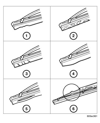
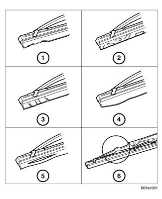
- Carefully inspect the wiper blades for any indications of worn or uneven edges (1), foreign material deposits (2), hardening or cracking (3), deformation or fatigue (4), or splitting (5). Inspect the wiper blade support components and the wiper arms for damage (6) or corrosion. If the wiper arms and blades are contaminated with any foreign material, clean them and the glass as required. (Refer to 08 - Electrical/8R - Wipers/Washers - Cleaning) . If a wiper blade or arm is damaged, or if corrosion is evident, replace the affected wiper arm or blade with a new unit. Do not attempt to repair a wiper arm or blade that is damaged or corroded.
-
Carefully lift the
wiper blade off of the glass. Note the action of the wiper arm hinge.
The wiper arm should pivot freely at the hinge, but with no lateral
looseness evident. If there is any binding evident in the wiper arm
hinge, or if there is evident lateral play in the wiper arm hinge,
replace the wiper arm.
CAUTION: Do not allow the wiper arm to spring back against the glass without the wiper blade in place or the glass may be damaged.
- Once proper hinge action of the wiper arm is confirmed, check the hinge for proper spring tension. Remove the wiper blade from the wiper arm. Either place a small postal scale between the blade end of the wiper arm and the glass, or carefully lift the blade end of the arm away from the glass using a small fish scale. On vehicles with unequal wiper arm lengths, be certain that measurements on both arms are taken at a point an equal distance from their wiper arm hinge pins. Compare the scale readings between the right and left wiper arms. Replace a wiper arm if it has comparatively lower spring tension, as evidenced by a lower scale reading.
-
After cleaning and
inspecting the wiper components and the glass, if the wiper blade
still fails to clear the glass without smearing, streaking, chattering,
hazing, or beading, replace the wiper blade.
WASHER SYSTEM
The washer system components should be inspected periodically, not just when washer performance problems are experienced. This inspection should include the following points:
- Check for ice or other foreign material in the washer reservoir. If contaminated, clean and flush the washer system. (Refer to 08 - Electrical/8R - Wipers/Washers - Cleaning) .
- Inspect the washer plumbing for pinched, leaking, deteriorated, or incorrectly routed hoses and damaged or disconnected hose fittings. Replace damaged or deteriorated hoses and hose fittings. Leaking washer hoses can sometimes be repaired by cutting the hose at the leak and splicing it back together using an in-line connector fitting. Similarly, sections of deteriorated hose can be cut out and replaced by splicing in new sections of hose using in-line connector fittings. Whenever routing a washer hose or a wire harness containing a washer hose, it must be routed away from hot, sharp, or moving parts. Also, sharp bends that might pinch the washer hose must be avoided.
REAR
REAR
WIPER SYSTEM
 |
The rear wiper blade and wiper arm should be inspected periodically, not just when wiper performance problems are experienced. This inspection should include the following points:
- Carefully inspect the wiper blade for any indications of worn or uneven edges (1), foreign material deposits (2), hardening or cracking (3), deformation or fatigue (4), or splitting (5). Inspect the wiper blade support components and the wiper arm for damage (6). If the wiper arm and blade are contaminated with any foreign material, clean them and the glass as required. (Refer to 08 - Electrical/8R - Wipers/Washers - Cleaning) . If the wiper blade or arm is damaged, replace it with a new unit. Do not attempt to repair a wiper arm or blade that is damaged or corroded.
-
Carefully lift the
wiper blade off of the glass. Note the action of the wiper arm hinge.
The wiper arm should pivot freely at the hinge, but with no lateral
looseness evident. If there is any binding evident in the wiper arm
hinge, or there is evident lateral play in the wiper arm hinge, replace
the wiper arm.
CAUTION: Do not allow the wiper arm to spring back against the glass without the wiper blade in place or the glass may be damaged.
- Once proper hinge action of the wiper arm is confirmed, check the hinge for proper spring tension. The spring tension of the wiper arm should be sufficient to cause the rubber squeegee to conform to the curvature of the glass. Replace a wiper arm if it has insufficient spring tension to maintain contact between the squeegee and the glass.
-
After cleaning and
inspecting the wiper components and the glass, if the wiper blade
still fails to clear the glass without smearing, streaking, chattering,
hazing, or beading, replace the wiper blade.
WASHER SYSTEM
The washer system components should be inspected periodically, not just when washer performance problems are experienced. This inspection should include the following points:
- Check for ice or other foreign material in the washer reservoir. If contaminated, clean and flush the washer system. (Refer to 08 - Electrical/8R - Wipers/Washers - Cleaning) .
- Inspect the washer plumbing for pinched, leaking, deteriorated, or incorrectly routed hoses and damaged or disconnected hose fittings. Replace damaged or deteriorated hoses and hose fittings. Leaking washer hoses can sometimes be repaired by cutting the hose at the leak and splicing it back together using an in-line connector fitting. Similarly, sections of deteriorated hose can be cut out and replaced by splicing in new sections of hose using in-line connector fittings. Whenever routing a washer hose or a wire harness containing a washer hose, it must be routed away from hot, sharp, or moving parts. Also, sharp bends that might pinch the washer hose must be avoided.