09 - Engine, 2.8L Diesel
- DESCRIPTION
- DUST COVERS AND CAPS
- ENGINE GASKET SURFACE PREPARATION
- COMPRESSION TEST
- SPECIFICATIONS
- TORQUE
- REMOVAL
- INSTALLATION
- SPECIAL TOOLS
DESCRIPTION
DESCRIPTION
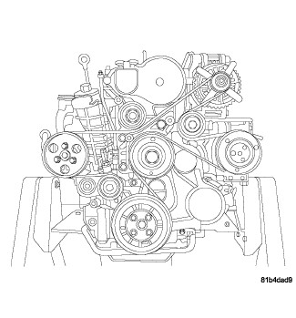 |
The 2.8L (2777cc) four-cylinder “common rail” direct injection engine is an in-line overhead valve design. The engine utilize a cast iron cylinder block. The engine has a one piece aluminum cylinder head with four valves per cylinder and dual overhead cam shafts. The 2.8L is turbocharged, intercooled and also equipped with a EGR cooler.
The identification stamp for the 2.8L is located on the left side of the engine block, above the starter. The engine code label is located on the front timing cover and is the same as the engine I.D. and serial number. There is also a fuel system label on the front timing cover used for fuel system identification during PCM programming.
DUST COVERS AND CAPS
DUST COVERS AND CAPS
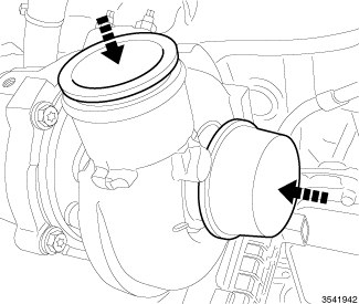 |
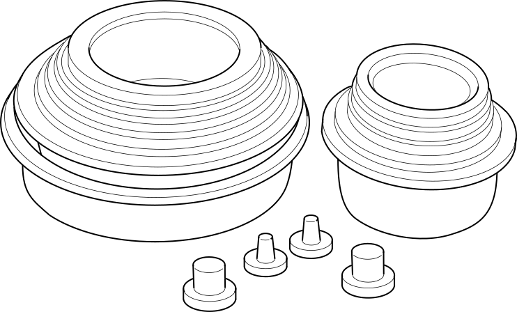
Due to the high amounts of failures caused by dust, dirt, moisture and other foreign debris being introduced to the engine during service. Covers or caps are needed to reduce the possible damage that can be caused or created.
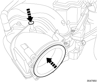 |
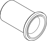
Covers over openings will reduce any possibilities for foreign materials to enter the engine systems. Using miller tool Set, Universal Protective Cap 10368 , Select the appropriated cover needed to the procedure.
ENGINE GASKET SURFACE PREPARATION
ENGINE GASKET SURFACE PREPARATION
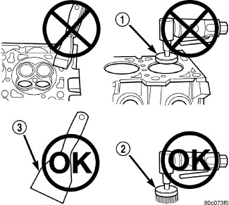 |
To ensure engine gasket sealing, proper surface preparation must be performed, especially with the use of aluminum engine components and multi-layer steel cylinder head gaskets.
Never use the following to clean gasket surfaces:
- Metal scraper
- Abrasive pad or paper to clean cylinder block and head
- High speed power tool with an abrasive pad (1), or a wire brush
| NOTE: |
Multi-Layer Steel (MLS) head gaskets require a scratch free sealing surface. |
Only use the following for cleaning gasket surfaces:
COMPRESSION TEST
COMPRESSION TEST
 |
- Warm up engine to operating temperature (approximately 80 °C, 176 °F).
- Shut off the engine.
- Disable the low pressure fuel pump.
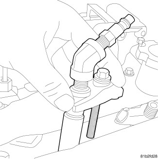
- Remove the fuel injectors (Refer to 14 - Fuel System/Fuel Injection/INJECTOR(S) , Fuel - Removal).
- Crank engine several times with the starter to eliminate combustion residues in the cylinders.
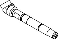
- Insert the Adapter, Compression Test VM.10010 into injector hole of cylinder to be tested. Install injector retainer bolts and tighten.
-
Test compression pressure by cranking engine with starter for at least 8 revolutions.
Cylinder compression Difference Between Cylinders
10 Bar (145 psi)
- Carry out test procedure at the remaining cylinders in the same way.
- Remove the Adapter, Compression Test VM.10010 from cylinder head.
-
Install injectors (Refer to 14 - Fuel System/Fuel Injection/INJECTOR(S)
, Fuel - Installation).
SPECIFICATIONS
SPECIFICATIONS
| 2.8L Engine Specifications | |
|---|---|
|
Engine |
2.8L JK/KK |
|
Engine Type |
2.8L — 16 Valves |
|
Displacement |
2777 cc |
|
Bore |
94.00 |
|
Stroke |
100.05 |
|
Power (VGT) JK - KK |
147 kW (200CV) @ 3600 RPM |
|
Torque (ATX) JK - KK |
460 N·m @ 1600 - 2600 RPM |
|
Torque (MTX) JK - KK |
410 N·m @ 2000 - 3200 RPM |
|
Cylinders |
4 In line |
|
Injection Order |
1–3–4–2 |
|
Compression Ratio |
16.5:1 |
|
Vacuum at idle |
600 mm/HG (27.5 In/HG) @ 800 RPM |
|
Idle Speed (ATX) JK |
760 +/- 50 RPM |
|
Idle Speed (ATX) KK |
730 +/- 50 RPM |
|
Idle Speed (MTX) JK - KK |
875 +/- 50 RPM |
|
Maximum RPM in Gear |
6600 RPM |
|
Maximum RPM in neutral |
ATX 3000 MTX 3000 |
|
Belt tension |
Automatic Belt Tensioner |
|
Thermostat opening |
90°C +/- 2°C |
|
Generator Rating |
Denso 12V-180A; JK MTX 12V-220A |
|
Emissions Level |
EU5 |
|
Block configuration/Material |
Open/Cast Iron |
|
Cylinder Head |
Dual Overhead Cam |
|
Timing System |
Belt |
|
Fuel System |
CP1H HP pump, 1800 bar, Piezo Injectors CRI 13.2 |
|
Fuel Supply |
Electric Fuel Pump In the Fuel Tank |
|
Electronic Control Unit |
EDC 17 |
|
Timing System |
Belt Driven DOHC Overhead Camshaft |
|
Air Intake |
Dry Filter With turbocharger and Charge Air Cooler |
|
Fuel System |
Direct Fuel Injection Common Rail System |
|
Emission Devices |
Cooled EGR (electric DC motor) Electric Intake Throttle Fast Metallic Glow plugs |
|
Combustion Cycle |
4 Stroke |
|
Cylinder Compression Difference Between Cylinders |
10 bar (145 psi) |
|
Cooling System |
Water Cooling |
|
Turbocharger |
Single VGT with REA |
|
Intake Ports |
Aluminum heads with traditional dual side intake and exhaust ports. One intake port is helical and the other has a directed entry. |
|
Crankshaft |
8 Counterweights with an incorporated balance shaft gear. |
|
Camshafts |
2 overhead camshafts with axial front bearings and identical camshaft caps, finger followers, and hydraulic lifters. |
|
Intake AND Exhaust Valves |
Flat with fire deck face. |
|
Intake Manifold |
Plastic, with integrated swirl control flap and actuator |
|
Lubrication |
Pressure Lubricated By Rotary Pump |
|
Minimum Oil Pressure (warm) |
0.7 BAR at idle / 2.5 BAR at 3800 rpm |
|
Engine Rotation |
Clockwise Viewed From Front Cover |
|
Engine Oil Capacity With Filter |
6.6L (7 Quarts) |
| 2.8L Engine Specifications | |
|---|---|
|
Cylinder Head |
|
|
Cylinder head height |
135.5 mm (5.334 in.) |
|
Cylinder head flatness deformation tolerance |
0.075 mm (0.003 in.) |
|
Cylinder Head Gasket Thickness |
|
|
0 Hole |
1.10 mm ( 0.043 in) |
|
1 Hole |
1.20 mm (0.047 in) |
|
2 Holes |
1.30 mm (0.051 in) |
|
Intake Manifold |
|
|
Intake manifold flatness deformation tolerance |
0.075 mm (0.003 in.) |
|
Exhaust Manifold |
|
|
Exhaust manifold flatness deformation tolerance |
0.075 mm (0.003 in.) |
|
Tappets |
|
|
Hydraulic tappet outside diameters |
11.994 mm +/- 0.06 mm (0.472 in +/- 0.002) |
|
Valves |
|
|
Intake valve face angle |
45°30' |
|
Exhaust valve face angle |
45°30' |
|
Intake Valve Head Diameter |
32 mm (1.25 in.) |
|
Exhaust Valve Head Diameter |
29.4 mm (1.15 in.) |
|
Intake Valve Stem Diameter |
5.97 mm (0.235 in.) |
|
Exhaust Valve Stem Diameter |
5.96 mm (0.235 in.) |
|
Intake Valve Guide Stem Clearance |
|
|
Min |
0.030 mm (0.0012 in.) |
|
Max |
0.060 mm (0.0024 in.) |
|
Exhaust Valve Guide Stem Clearance |
|
|
Min |
0.040 mm (0.0016 in.) |
|
Max |
0.070 mm (0.0028 in.) |
|
Valve Springs |
|
|
Free Length |
50.8 mm (2 in.) |
|
Closed Valve |
38 mm (1.49 in.) |
|
Opened Valve |
29 mm (1.14 in.) |
|
Camshafts |
|
|
Camshaft End Play |
|
|
Max |
0.350 mm (0.014 in.) |
|
Min |
0.150 mm (0.006 in.) |
|
Outer Journal Diameter (at crankshaft) |
25.95 mm +/– 0.01 mm (1.021 mm +/- .0004 in) |
|
Inner Journal Diameter (at cylinder head) |
26.00 mm + 0.015 mm (1.027 mm .0006 in) |
|
Crankshaft Journal Clearance |
|
|
Max |
0.075 mm (0.003 in.) |
|
Min |
0.030 mm (0.0012 in) |
|
Connecting Rods |
|
|
Connecting Rod Diameter (Small End) |
32 mm (1.26 in.) |
|
Connecting Rod Diameter (Large End) |
57.563 mm ( 2.266 in.) |
|
Piston Pin |
|
|
Diameter |
32 mm (1.26 in.) |
|
Length |
70.7 mm - 71.00 mm (2.78 in — 2.79 in.) |
|
Crankshaft |
|
|
End Play |
0.1 mm — 0.33 mm (0.004 in. — 0.013 in.) |
|
Bearing Selection (Refer to 09 - Engine/Engine Block - Standard Procedure) |
|
|
Engine Block |
|
|
Cylinder Bore Internal Diameter |
94 mm (3.700 in.) |
|
Cylinder Bore Out-Of-Round |
0.007 mm (0.0003 in.) |
|
Oversized Piston |
+0.40 mm (+0.015 in.) |
|
Fuel System |
|
|
Injection Pressure |
1800 Bar |
|
High Pressure Pump |
CP1H |
|
ECU |
EDC17 |
|
Injectors |
Piezo CRI 3.2 |
|
Glow Plugs |
|
|
Make/Type |
Bosch / GLP2 HS |
|
Voltage |
4.4V |
|
Lubrication System |
|
|
Oil Pump Outer Rotor End Play |
|
|
Min |
0.01 (0.0004 in.) |
|
Max |
0.09 (0.0036 in.) |
|
Oil Pump Inner Rotor End Play |
|
|
Max |
0.01 mm (0.0004 in.) |
|
Min |
0.09 mm (0.0036 in.) |
|
Oil Pump Outer Rotor to Body Diameter Clearance |
|
|
Max |
0.130 mm (0.052 in.) |
|
Min |
0.230 mm (0.0091 in) |
|
Oil Pressure Relief Valve |
|
|
Opening Pressure |
5 Bar |
|
Oil Pressure Valve Spring Free Length |
46.8 mm (1.84 in) |
|
Minimum Oil Pressure (Warm) |
|
|
at Idle |
0.7 Bar |
|
at 3800 RPM |
2.5 Bar |
|
Cooling System |
|
|
Thermostat Opening Temperature |
90°C +/- 2 (194°F +/-2) |
|
Pressure Cap Setting |
1.2 Bar |
|
Engine Oil |
|
|
Specification (Refer to 04 - Vehicle Quick Reference/Capacities and Recommended Fluids - Description) |
|
|
Coolant |
|
|
Specification (Refer to 04 - Vehicle Quick Reference/Capacities and Recommended Fluids - Description) |
|
|
Cylinder Head Gasket Selection |
||
|---|---|---|
|
Millimeters |
Inches |
|
|
DISTANCE FROM PISTON AT TDC TO CYLINDER BLOCK |
0.300 — 0.399 |
0.0119 — 0.0158 |
|
CYLINDER HEAD GASKET THICKNESS |
1.10 |
0.0434 |
|
PISTON CLEARANCE |
0.700–0.800 |
0.0276 —0.0315 |
|
DISTANCE FROM PISTON AT TDC TO CYLINDER BLOCK |
0.400 — 0.499 |
0.0158 — 0.0197 |
|
CYLINDER HEAD GASKET THICKNESS |
1.20 |
0.0473 |
|
PISTON CLEARANCE |
0.701–0.800 |
0.0276 —0.0315 |
|
DISTANCE FROM PISTON AT TDC TO CYLINDER BLOCK |
0.500 — 0.600 |
0.0197 — 0.0237 |
|
CYLINDER HEAD GASKET THICKNESS |
1.30 |
0.0512 |
|
PISTON CLEARANCE |
0.700–0.800 |
0.0276 —0.0315 |
TORQUE
TORQUE
ENGINE BLOCK
| DESCRIPTION | N·m | Ft. Lbs. | In. Lbs. |
|---|---|---|---|
|
Air Temp/Pressure Sensor |
12 |
— |
106 |
|
Balance Shaft Bolts |
33 |
24 |
— |
|
Connecting Rod Bearing Cap Bolts |
(Refer to 09 - Engine/Engine Block/ROD, Piston and Connecting - Installation) |
||
|
Dipstick Tube Bolt (block) |
33 |
24 |
— |
|
Dipstick Tube Bolt (sump) |
11 |
— |
97 |
|
Engine Block Plug |
30 |
22 |
— |
|
Engine Mount Bolts |
54 |
40 |
— |
|
Lower Oil Pan Bolts |
|||
|
Main Bearing Cap Bolts |
(Refer to 09 - Engine/Engine Block/CRANKSHAFT - Installation) |
||
|
Oil Cooler Bolts |
12 |
— |
106 |
|
Oil Cooler Coolant Adapter Tube at Oil Filter Housing Bolt |
11 |
— |
97 |
|
Oil Cooler Coolant Tube Bolts |
15 |
— |
133 |
|
Oil Drain Plug |
54 |
40 |
— |
|
Oil Filter Cap |
25 |
18 |
— |
|
Oil Filter Housing Bolts |
33 |
24 |
— |
|
Oil Jet Bolt |
11 |
— |
97 |
|
Oil Pickup Tube Bolt |
15 |
— |
133 |
|
Oil Pressure Sensor |
14 |
— |
124 |
|
Oil Temperature Sensor |
20 |
— |
177 |
|
Upper Oil Pan (M6 bolt) |
15 |
— |
133 |
|
Upper Oil Pan (M8 bolt) |
32 |
24 |
— |
|
Wire Harness Support Bracket Bolt |
45 |
33 |
— |
CYLINDER HEAD
| DESCRIPTION | N·m | Ft. Lbs. | In. Lbs. |
|---|---|---|---|
|
Camshaft Bearing Cap Bolts |
11 |
— |
97 |
|
Camshaft Position Sensor Bolt |
11 |
— |
97 |
|
Camshaft Sprocket Bolt |
80 |
59 |
— |
|
Cylinder Head Bolts |
|||
|
Cylinder Head Cover Bolts |
11 |
— |
97 |
|
EGR Air Flow Control Valve Bolts |
11 |
— |
97 |
|
EGR Cooler Manifold Nuts |
25 |
18 |
— |
|
EGR Cooler Manifold Elbow Bolt |
11 |
— |
97 |
|
EGR Cooler Manifold Support Bracket Bolts |
45 |
33 |
— |
|
EGR Cooler Support Bracket Bolts |
25 |
18 |
— |
|
Exhaust Manifold Nuts |
36 |
27 |
— |
|
Front Camshaft Journal Bolts |
11 |
— |
97 |
|
Fuel injector Bolt |
33 |
24 |
— |
|
Fuel Rail Nuts |
24 |
18 |
— |
|
Fuel Tubes at Fuel Injector |
28 |
20 |
— |
|
Fuel Tubes at Fuel Rail |
5 + 75° |
— |
44 + 75° |
|
Glow Plugs |
14 |
— |
124 |
|
High Pressure Fuel Line Bracket Bolt |
15 |
— |
133 |
|
High Pressure Fuel Feed Line at Fuel Rail |
5 + 75° |
— |
44 + 75° |
|
High Pressure Fuel Feed Line at the High Pressure Pump |
28 |
20 |
— |
|
Intake Manifold Nuts |
(Refer to 09 - Engine/Manifolds/MANIFOLD, Intake - Installation) |
||
|
Turbocharger Nuts |
25 |
18 |
— |
|
Turbocharger Adapter (oil feed line to engine block connection) |
54 |
40 |
— |
|
Turbocharger Brace Bolts |
32 |
24 |
— |
|
Turbocharger Oil Feed Line at Engine Block |
32 |
24 |
— |
|
Turbocharger Oil Feed Line Nipple at Engine Block |
54 |
40 |
— |
|
Turbocharger Oil Feed Line Banjo Bolt at the Turbocharger |
25 |
18 |
— |
|
Turbocharger Oil Return Line Bolts |
15 |
— |
133 |
|
Vacuum Tube Nut |
11 |
— |
97 |
FRONT ENGINE
| DESCRIPTION | N·m | Ft. Lbs. | In. Lbs. |
|---|---|---|---|
|
Crankshaft Pulley Bolt |
32 |
24 |
— |
|
Crankshaft Sprocket Bolt |
100 + 120° |
74 + 120° |
— |
|
Front Cover Bolts |
33 |
24 |
— |
|
Fuel Quantity Solenoid Bolts |
7 |
— |
62 |
|
High Pressure Fuel Pump Blocker Nuts |
25 |
18 |
— |
|
High Pressure Fuel Pump Nuts |
25 |
18 |
— |
|
High Pressure Fuel Pump Sprocket Nut |
88 |
65 |
— |
|
Inner Front Cover Bolts |
11 |
— |
97 |
|
Outer Front Cover Bolts (lower) |
8 |
— |
71 |
|
Outer Front Cover Bolts (upper) |
8 |
— |
71 |
|
Timing Belt Tensioner Bolt |
28 |
21 |
— |
|
Water Pump Bolts |
32 |
24 |
— |
REAR ENGINE
| DESCRIPTION | N·m | Ft. Lbs. | In. Lbs. |
|---|---|---|---|
|
Crankshaft Sensor Bolt |
11 |
— |
97 |
|
CKP Cover Plate Bolts |
15 |
— |
133 |
|
Flex Plate (ATX) |
(Refer to 09 - Engine/Engine Block/FLEXPLATE - Installation) |
||
|
Rear Seal Cover Bolts |
15 |
— |
133 |
|
Trans Adapter Plate (allen bolts) |
79 |
58 |
— |
|
Trans Adapter Plate (hex bolt) |
69 |
51 |
— |
ACCESSORY DRIVE
| DESCRIPTION | N·m | Ft. Lbs. | In. Lbs. |
|---|---|---|---|
|
A/C Compressor Bolts |
28 |
21 |
— |
|
A/C Compressor Nuts |
28 |
21 |
— |
|
A/C Compressor/Generator Bracket Bolts |
45 |
33 |
— |
|
Accessory Drive Belt Tensioner Bolt |
45 |
33 |
— |
|
Accessory Drive Idler Pulley Bolt |
45 |
33 |
— |
|
Front Engine Lifting Bracket Bolts |
68 |
50 |
— |
|
Generator Bolts |
33 |
24 |
— |
|
Power Steering Pump Bolts |
33 |
24 |
— |
|
Power Steering Pump Pulley Bolts |
33 |
24 |
— |
|
Viscous Fan Drive Pulley Bolts |
45 |
33 |
— |
REMOVAL
REMOVAL
- Disconnect the negative and positive battery cables.
- Remove the battery.
- Recover the refrigerant (Refer to 24 - Heating and Air Conditioning/Plumbing - Standard Procedure) .
- On manual transmission models, remove the shiftier level (Refer to 21 - Transmission and Transfer Case/Manual/LEVER, Shift - Removal) .
-
Remove the air cleaner body (Refer to 09 - Engine/Air Intake System/BODY, Air Cleaner - Removal)
.
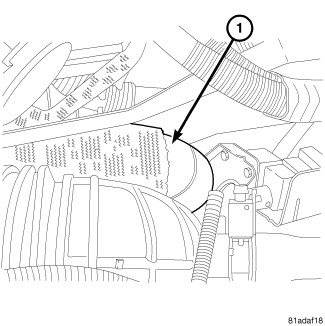
- Remove the turbocharger air inlet tube at turbo.
- Remove the right side Charge Air Cooler (CAC) hose (1).
- Raise and support the vehicle (Refer to 04 - Vehicle Quick Reference/Hoisting - Standard Procedure) .
- Remove the front lower splash shield.
- Drain the coolan (Refer to 07 - Cooling - Standard Procedure)
- Drain the engine oil.
- Using a new copper sealing washer, tighten oil drain plug to 54 N·m (40 ft. lbs.).
- Remove the transmission skid plate.
-
Remove the catalytic converter (Refer to 11 - Exhaust System/CONVERTER, Catalytic - Removal)
.
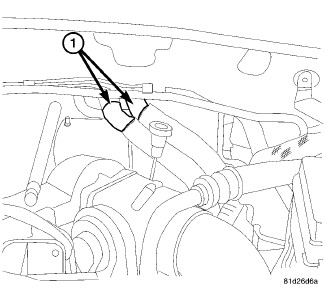
- Remove the coolant recovery bottle (Refer to 07 - Cooling/Engine/BOTTLE, Coolant Recovery - Removal) .
- Disconnect the engine harness connectors at right side firewall.
- Disconnect the coolant hoses (1) from the heater core.
- Disconnect the upper radiator hose at radiator.
- Remove the fan assembly (Refer to 07 - Cooling/Engine/FAN, Cooling - Removal) .
-
Remove the serpentine belt (Refer to 07 - Cooling/Accessory Drive/BELT, Serpentine - Removal)
.
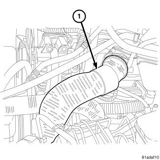
- Remove the left side Charge Air Cooler (CAC) hose (1) at EGR air flow control valve.
-
Remove the left side charge air cooler hose at cooler.
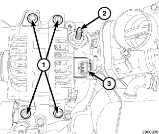
- Remove the generator (Refer to 08 - Electrical/8F - Engine Systems/Charging/GENERATOR - Removal) .
-
Remove the A/C compressor (Refer to 24 - Heating and Air Conditioning/Plumbing/COMPRESSOR, A/C - Removal)
.
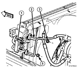
- Remove the A/C suction and liquid line from the condenser.
- Remove the A/C suction and liquid lines from the evaporator.
-
Remove and discard gasket/O-ring seals and install protective caps over openings.
-
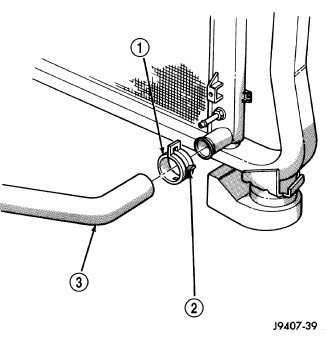
Remove the lower radiator hose (3) at radiator.
-
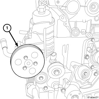
Remove the power steering pump pulley (1).
-
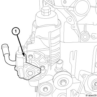
Remove the power steering pump (1) and position aside.
-
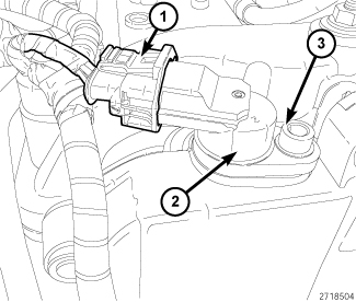
Disconnect the Camshaft Position Sensor (CMP) harness connector (1).
-
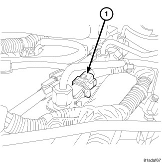
Disconnect the fuel injector harness connectors.
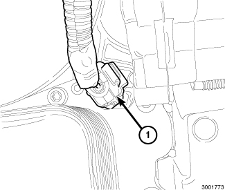
-
Disconnect the oil temperature sensor harness connector (1).
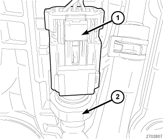
-
Disconnect the oil pressure switch harness connector (1).
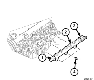
- Disconnect the fuel pressure sensor harness connector (1).
-
Disconnect the fuel pressure regulator harness connector (3).
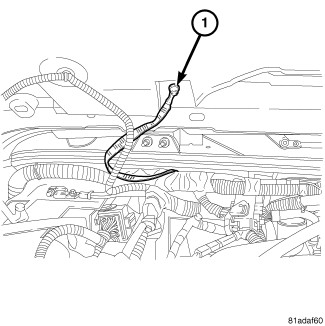
- Disconnect the turbocharger actuator connector.
- Disconnect the EGR airflow control valve harness connector.
- Disconnect the IAT/BPS harness connector.
- Disconnect the ground strap between the cowl and hood.
- Disconnect the glow plug harness connectors.
- Position aside the upper engine harness.
-
Disconnect the brake booster vacuum hose.
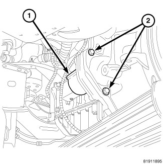
NOTE: Starter shown for a manual transmission.
-
Remove the starter (Refer to 08 - Electrical/8F - Engine Systems/Starting/STARTER - Removal)
.
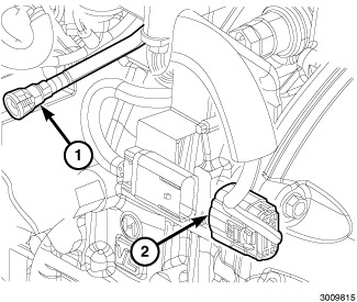
- Disconnect the fuel supply and return tubes to high pressure pump.
- Disconnect the fuel rail return line (1).
- Disconnect the multi-sensor jumper harness connector (2).
- Remove bolt, and the engine ground cable at engine block.
-
Remove the crankshaft position sensor (Refer to 14 - Fuel System/Fuel Injection/SENSOR, Crankshaft Position - Removal)
.
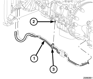
NOTE: The plastic clip that secures the transmission oil cooler lines to oil pan stud/bolt is a one time use clip that need to be replace each time the line is removed.
-
On automatic transmission models, remove the transmission cooler line (1) from oil pan stud (2) and discard clip (3).
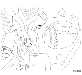
- Remove the torque converter to flex plate bolts.
- On manual transmission models, remove the transfer skid plate.
-
On manual transmission models, remove the manual transmission (Refer to 21 - Transmission and Transfer Case/Manual - Removal)
.
-
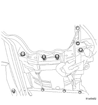
Remove the bell housing bolts.
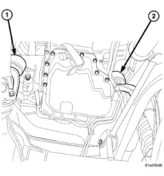
- Remove the nut from the left engine mount.
- Remove the nut from the right engine mount.
- Install a suitable engine lifting device.
-
Remove the engine.
INSTALLATION
INSTALLATION
|
- Install the engine.
- Remove the engine lift.
- Install the right engine mount nut. Tighten nut to 54 N·m (40 ft. lbs.).
-
Install the left engine
mount nut. Tighten nut to 54 N·m (40 ft. lbs.).
- Install the bell housing bolts:
-
Install the transmission
oil line bracket at the oil pan.
- On manual transmission models, install the manual transmission (Refer to 21 - Transmission and Transfer Case/Manual - Installation) .
- On manual transmission models, install the water and fuel separator (Refer to 14 - Fuel System/Fuel Delivery/SEPARATOR and FILTER, Fuel and Water - Installation) .
- On manual transmission models, install the transfer skid plate.
-
Install the torque
converter to flex plate bolts. Tighten bolts to 31 N·m (23 ft. lbs.).
- Install the crankshaft position sensor (Refer to 14 - Fuel System/Fuel Injection/SENSOR, Crankshaft Position - Installation) .
- Install the engine ground cable at engine block.
- Connect the fuel rail return line.
- Connect the fuel supply and return lines to high pressure pump.
-
Install the starter (Refer to 08 - Electrical/8F - Engine
Systems/Starting/STARTER - Installation)
.
- Connect the brake booster vacuum hose.
- Position the engine wiring harness.
- Connect the glow plug harness connectors.
-
Connect the ground
strap between the cowl and hood.
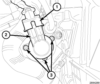
- Connect the fuel quantity solenoid.
- Connect the IAT/BPS harness connector (1).
- Connect the EGR airflow control valve harness connector.
-
Connect the turbocharger
actuator connector.
- Connect the fuel pressure regulator harness connector (3).
-
Connect the fuel pressure
sensor harness connector (1).
-
Connect the oil pressure
switch harness connector (1).
- Connect the oil temperature sensor harness connector (1).
- Connect the coolant temperature sensor harness connector.
-
Connect the EGR bypass
valve harness connector.
-
Connect the fuel injector
harness connectors.
- Connect the Camshaft Position Sensor (CMP) harness connector (1).
-
Connect the EGR valve
harness connector.
-
Install the power steering
pump (1). Tighten the bolts to 33 N·m (24 ft. lbs.).
-
Install the power steering
pump pulley (1). Tighten bolts to 33 N·m (24 ft. lbs.).
-
Install the lower radiator
hose at radiator.
- Remove protective caps and lubricate install new gasket/O-ring seals.
- Install the A/C suction and liquid lines to the expansion valve. Tighten the nut to 8 N·m (70 in. lbs.).
-
Install the A/C suction
and liquid line from the condenser. Tighten the nuts to 23 N·m (17
ft. lbs.).
- Install the A/C compressor (Refer to 24 - Heating and Air Conditioning/Plumbing/COMPRESSOR, A/C - Installation) .
-
Install the generator (Refer to 08 - Electrical/8F - Engine
Systems/Charging/GENERATOR - Installation)
.
- Install the left side charge air cooler hose at cooler.
-
Install the left side
charge air cooler hose at EGR air flow control valve.
- Install the serpentine belt (Refer to 07 - Cooling/Accessory Drive/BELT, Serpentine - Installation) .
- Install the fan assembly (Refer to 07 - Cooling/Engine/FAN, Cooling - Installation) .
- Connect the upper radiator hose at radiator.
- Install the coolant hoses (1) to the heater core.
- Connect the engine harness connectors at right side firewall.
-
Install the coolant
recovery bottle (Refer to 07
- Cooling/Engine/BOTTLE, Coolant Recovery - Installation)
.
- Install the left front wheel house splash shield (Refer to 23 - Body/Exterior/SHIELD, Splash - Installation) .
- Install the catalytic converter (Refer to 11 - Exhaust System/CONVERTER, Catalytic - Installation) .
- Install the transmission skid plate.
- Install the front lower splash shield.
- Install the right side charge air cooler hose.
- Install the turbocharger air inlet tube at turbocharger.
- Install the air cleaner body (Refer to 09 - Engine/Air Intake System/BODY, Air Cleaner - Installation) .
- On manual transmission models, install the shiftier lever (Refer to 21 - Transmission and Transfer Case/Manual/LEVER, Shift - Installation) .
- Fill the coolant (Refer to 07 - Cooling - Standard Procedure) .
- Fill the with recommended engine oil.
- Charge the A/C system (Refer to 24 - Heating and Air Conditioning/Plumbing - Standard Procedure) .
- Install the battery.
- Connect the positive and negative battery cables.
-
Start the engine and
check for leaks.