INSTALLATION
INSTALLATION
If the original engine has experienced a catastrophic
failure or an individual failure with the piston, cylinder bore, engine
block, valve or valve seat, the intake manifold MUST be replaced with
a new manifold.
CAUTION:
 |
| NOTE: |
If installing a replacement engine, transfer components such as engine mount isolators, block heater, accessories, heater hoses and tubes to the replacement engine. |
-
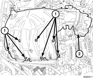
If required, remove
the upper intake manifold (2) (Refer to 09 - Engine/Manifolds/MANIFOLD, Intake - Removal)
-
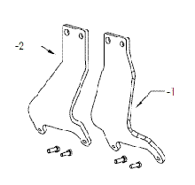
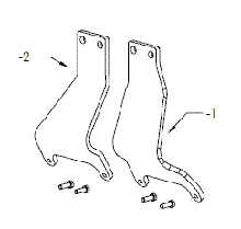
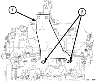
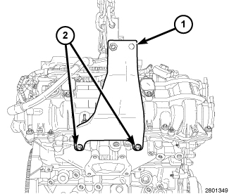
Install the Driver
Side Engine Lifting Bracket 10242-1 (1) on the LH cylinder head with bolts (2) provided with the
Engine Lifting Bracket. Tighten the bolts to 21 N·m (15 ft. lbs.).
-
Install the Passenger
Side Engine Lifting Bracket 10242-2 (1) on the RH cylinder head with bolts (2) from the Engine
Lifting Bracket. Tighten the bolts to 21 N·m (15 ft. lbs.).
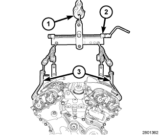
- Position a load-leveling lifting sling (2), such as OTC® 4305 Engine Load Leveler or equivalent, between the engine lifting brackets (3) and an engine hoist (1).
-
Reposition the main
wire harness to the rear of the engine compartment.
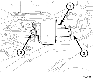
NOTE: Right engine mount shown, left engine mount similar.
- Position the engine in the vehicle. If equipped with an automatic transmission, align the two locator dowels into the transmission housing.
- Align the left and right engine mount isolators (1) within the frame mounting brackets and lower the engine so the weight is resting on the mounting bolts (2).
-
Tighten the left and
right engine mount nuts (3) to 61 N·m (45 ft. lbs.).
-
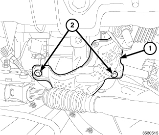
Install the engine
mount heatshield (1) to the left engine mount with two bolts (2) tightened
to 12 N·m (106 in. lbs.).
- Raise and support the vehicle (Refer to 04 - Vehicle Quick Reference/Hoisting - Standard Procedure) .
- Install the manual transmission, if equipped (Refer to 21 - Transmission and Transfer Case/Manual - Installation) .
-
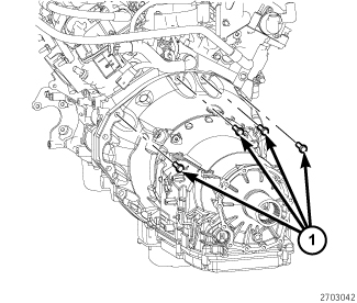
If equipped with an
automatic transmission, install the four upper transmission to engine
bolts (1). Tighten the bolts to 55 N·m (41 ft. lbs.).
-
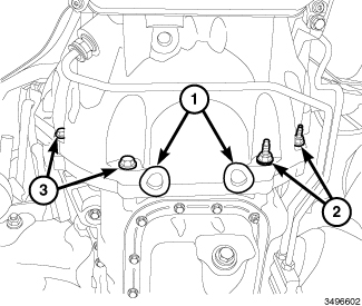
If equipped with an
automatic transmission;
- Install four transmission to the engine oil pan bolts (2 and 3) and tighten to 55 N·m (41 ft. lbs.).
-
Install two rubber
plugs (1) covering the rear oil seal retainer flange bolts.
-
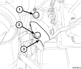
If equipped with an
automatic transmission;
- Install the side engine to transmission bolt (1). Tighten the bolt to 55 N·m (41 ft. lbs.).
-
Install the torque
converter dust shield (3) with the bolt (2). Tighten the bolt to 12
N·m (106 in. lbs.).
-
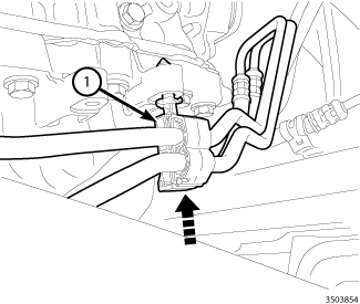
If equipped with an
automatic transmission, engage the transmission cooler line retainer
(1) to the oil pan flange.
-
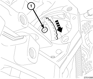
If equipped with an
automatic transmission, rotate the crankshaft in a clockwise direction
and install the six torque converter bolts (1) through the starter
mounting. Tighten the bolts to 42 N·m (31 ft. lbs.).
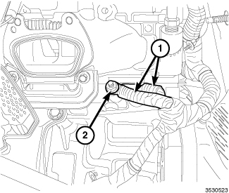
- Connect the power cord to the engine block heater (if equipped).
- Install the ground straps (1) with one nut (2) tightened to 12 N·m (106 in. lbs.).
-
Install the starter (Refer to 08 - Electrical/8F - Engine
Systems/Starting/STARTER - Installation)
.
-
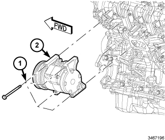
Install the A/C compressor
(2) onto the engine with four bolts (1) tightened to 28 N·m (21 ft.
lbs.).
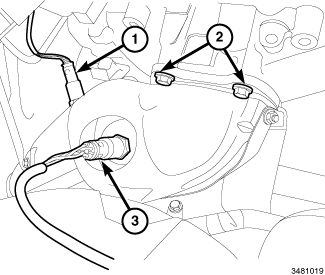
NOTE: Right catalytic converter shown, left catalytic converter similar.
- Install the right and left catalytic converters (Refer to 11 - Exhaust System/CONVERTER, Catalytic - Installation) .
-
Connect the right and
left upstream (3) and downstream (1) oxygen sensor connectors to the
main wire harness.
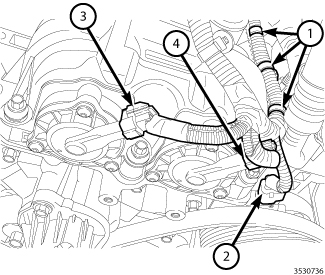
- Route the main wire harness on the left side of the engine.
- Connect the A/C compressor electrical connector (2).
- Connect the left exhaust variable valve timing solenoid electrical connector (4).
- Connect the left intake variable valve timing solenoid electrical connector (3).
-
Engage three wire harness
retainers (1) to the left cylinder head cover.
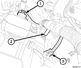
- Connect the Engine Coolant Temperature (ECT) sensor connector (3).
- Connect the left Camshaft Position (CMP) sensor (1).
-
Engage the main wire
harness retainer (2) to the cylinder head cover mounting stud.
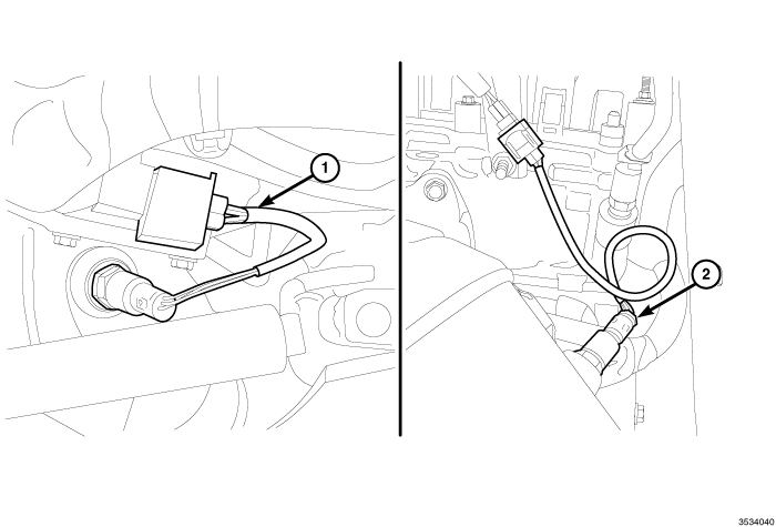
-
Connect the left upstream
oxygen sensor (1) and the left downstream oxygen sensor (2) electrical
connectors.
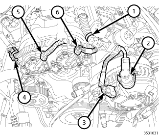
- Route the main wire harness on the right side of the engine.
- Install the B+ terminal to the generator stud (2) and tighten the nut to 11 N·m (97 In. lbs.).
- Connect the field circuit connector (3) to the generator.
- Connect the right exhaust variable valve timing solenoid electrical connector (5).
- Connect the right intake variable valve timing solenoid electrical connector (6).
-
Engage the wire harness
retainers (1 and 4) to the right cylinder head cover.
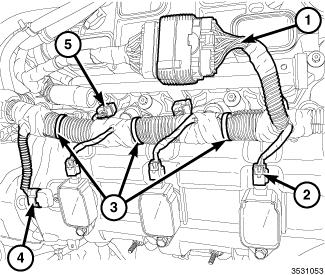
- Connect three fuel injector electrical connectors (5).
- Connect three ignition coil electrical connectors (2).
- Connect the electrical connector (4) to the right Camshaft Position (CMP) sensor.
- Connect the main harness to the engine injection/ignition harness (1).
-
Engage three main wire
harness retainers (3) to the right cylinder head cover.
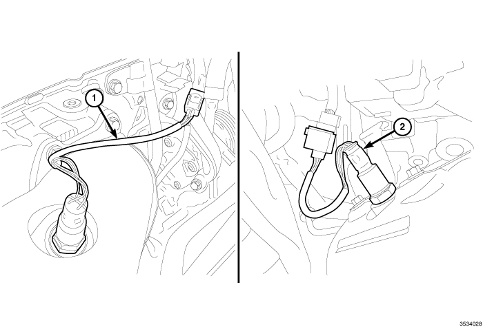
-
Connect the right upstream
oxygen sensor (1) and the right downstream oxygen sensor (2) electrical
connectors.
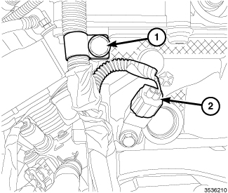
- Secure the main wire harness retainer to the rear of the right cylinder head with the bolt (1) tightened to 12 N·m (106 in. lbs.).
-
Connect the electrical
connector (2) to the ignition coil capacitor.
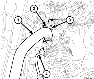
- Position the power steering pump (with bracket) and install the upper power steering pump bracket retaining bolts (3). Do not tighten at this time.
-
Engage the wiring harness
routing retainer (2) to the power steering pump bracket.
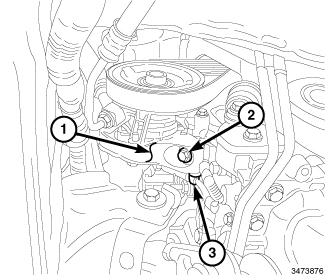
- Raise and support the vehicle (Refer to 04 - Vehicle Quick Reference/Hoisting - Standard Procedure) .
- Engage the wiring harness routing retainer (3) to the power steering pump bracket (1).
- Install the lower power steering pump retaining bolt (2) and tighten all three retaining bolts to 24 N·m (18 ft. lbs.).
-
Install the accessory
drive belt (Refer to 07 - Cooling/Accessory
Drive/BELT, Serpentine - Installation)
.
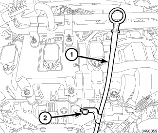
-
Install the oil level
indicator (1) with the bolt (2) tightened to 12 N·m (106 in. lbs.).
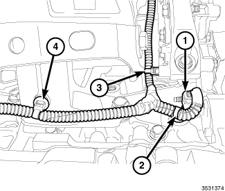
- Connect the oil pump solenoid electrical connector (1).
-
Engage one wire harness
retainer (2) to the engine block, one wire harness retainer (3) to
the power steering pump mounting bracket and one wire harness retainer
(4) to the right engine mount.
.
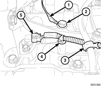
- Install the ground strap (1) with bolt (2) tightened to 12 N·m (106 in. lbs.).
- Connect the main wire harness to the Crankshaft Position (CKP) sensor (5).
-
Engage one main wire
harness retainer (4) to the engine block and one main wire harness
retainer (3) to the oil level indicator.
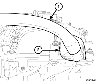
-
Install the PCV hose
(1) to the PCV valve (2).
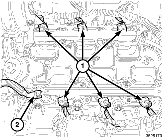
-
Connect the fuel supply
hose (2) to the fuel rail (Refer
to 14 - Fuel System/Fuel Delivery/FITTING, Quick Connect - Standard
Procedure)
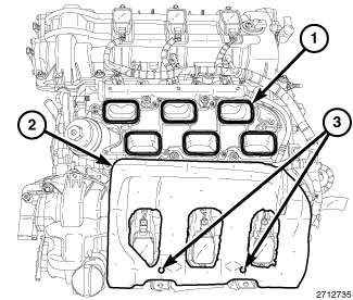
-
Install the insulator
(2) to the two alignment posts (3) on top of the LH cylinder head
cover.
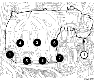
-
Install the upper intake
manifold and insulator (Refer
to 09 - Engine/Manifolds/MANIFOLD, Intake - Installation)
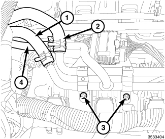
- Position the heater core tube assembly and install the heater core supply hose (2), heater core return hose (1) and oil cooler return hose (4).
-
Secure the heater core
tube assembly to the right upper intake manifold support bracket with
two nuts (3) tightened to 12 N·m (106 in. lbs.).
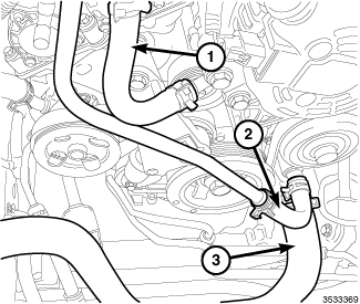
- Connect the heater core supply hose (1) to the heater core tube assembly.
- Connect the heater core return hose (2) to the heater core tube assembly.
-
Install the lower radiator
hose (3) to the engine coolant pump housing.
-
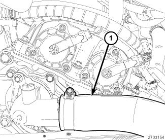
Install the upper radiator
hose (1) to the engine thermostat housing.
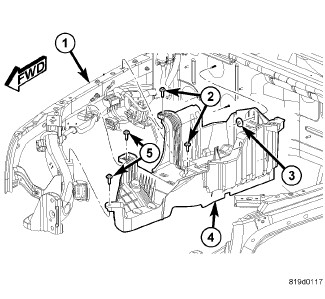
- Install the battery tray (4), Totally Integrated Power Module (TIPM) and battery (Refer to 08 - Electrical/8F - Engine Systems/Battery System/TRAY, Battery - Installation) .
-
Install the front wheelhouse
inner splash shields (Refer
to 23 - Body/Exterior/SHIELD, Splash - Installation)
.
-
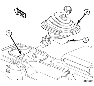
If equipped with a
manual transmission, install the shift lever (2) (Refer to 21 - Transmission and Transfer
Case/Manual/LEVER, Shift - Installation)
.
-
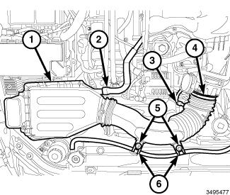
Install the air cleaner
body (1) (Refer to 09 - Engine/Air
Intake System/BODY, Air Cleaner - Installation)
.
- If removed, install the oil filter and fill the engine crankcase with the proper oil to the correct level (Refer to 09 - Engine/Lubrication/OIL - Standard Procedure)
- Fill the cooling system (Refer to 07 - Cooling - Standard Procedure) .
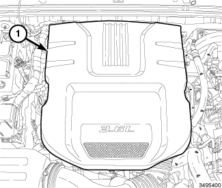
- Install the engine cover (1).
- Connect the negative battery cable and tighten nut to 5 N·m (45 in. lbs.).
- Run the engine until it reaches normal operating temperature. Check cooling system for correct fluid level (Refer to 07 - Cooling - Standard Procedure)
| NOTE: |
The Cam/Crank Variation
Relearn procedure must be performed using the scan tool anytime there
has been a repair/replacement made to a powertrain system, for example:
flywheel, valvetrain, camshaft and/or crankshaft sensors or components. |