Engine Block
DESCRIPTION
DESCRIPTION
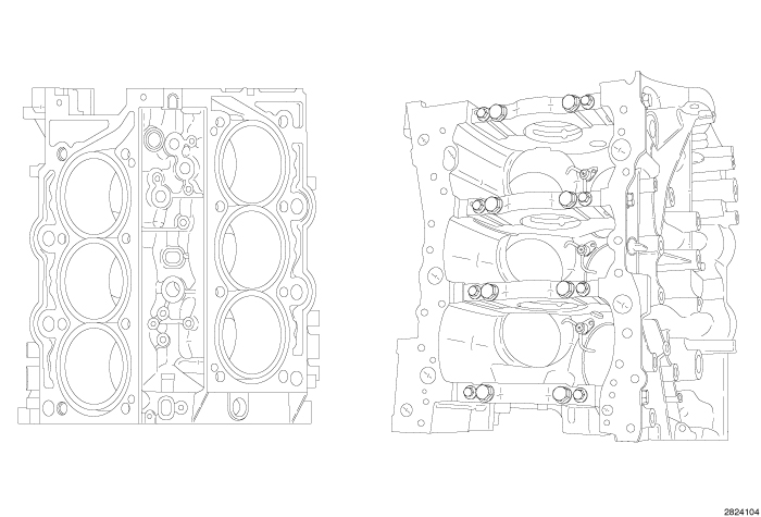 |
The cylinder block is a 60 degree high-pressure die cast aluminum design with cast steel cylinder liners. The leading side of the block is on the right side and houses cylinders 1, 3 and 5. The cylinder block is an open deck design with cut slots between each cylinder. Two knock sensors are located in the block valley. The cylinder block has three sets of piston cooling jets which are attached to the main oil gallery. The four powdered metal main bearing caps are a cross-bolted design and have directional arrows molded into the caps. The number 2 main bearing is the location for the two piece upper half thrust bearings. The thrust bearings are installed with the oil groves facing outward. The main bearing caps are a 6-bolt design and cross-bolted for improved lower end strength. There are three oil drain back drillings located on each of the cylinder banks.
MEASURING BEARING CLEARANCE USING PLASTIGAGE
MEASURING BEARING CLEARANCE USING PLASTIGAGE
 |
| NOTE: |
Typical crankshaft journal shown. |
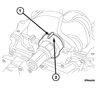
Engine crankshaft and connecting rod bearing clearances can be determined by the use of Plastigage or equivalent. The following is the recommended procedure for the use of Plastigage:
- Remove the oil film from surface to be checked. Plastigage is soluble in oil.
- Place a piece of Plastigage (1) across the entire width of the journal (In addition, suspected areas can be checked by placing the Plastigage in the suspected area). Plastigage must not crumble in use. If brittle, obtain fresh stock.
-
Torque the bearing cap bolts of the bearing being checked to the proper specifications (Refer to 09 - Engine - Specifications)
.
NOTE: DO NOT rotate the crankshaft. Plastigage will smear, causing inaccurate results.
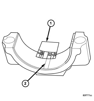
NOTE: Typical connecting rod cap shown.
- Remove the bearing cap and compare the width of the flattened Plastigage (2) with the scale provided on the package (1). Locate the band closest to the same width. This band shows the amount of clearance. Differences in readings between the ends indicate the amount of taper present or the possibility of foreign material trapped under the bearing insert.
-
Record all readings taken. Compare clearance measurements to engine specifications (Refer to 09 - Engine - Specifications)
.
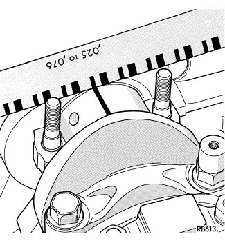
NOTE: Typical connecting rod journal shown.
NOTE: Plastigage is available in a variety of clearance ranges. Use the most appropriate range for the specifications you are checking. Plastigage generally is accompanied by two scales. One scale is in inches, the other is a metric scale.
- Install the proper bearings to achieve the specified bearing clearances.
-
Repeat the Plastigage measurement to verify your bearing selection prior to final assembly.
CYLINDER BORE HONING
CYLINDER BORE HONING
 |
Before honing, stuff plenty of clean shop towels under the bores and over the crankshaft to keep abrasive materials from entering the crankshaft area.
-
Used carefully, a cylinder bore sizing hone equipped with 220 grit stones, is the best tool for this job. In addition to deglazing, it will reduce taper and out-of-round, as well as removing light scuffing, scoring and scratches. Usually, a few strokes will clean up a bore and maintain the required limits.
CAUTION: DO NOT use rigid type hones to remove cylinder wall glaze.
-
Deglazing of the cylinder walls may be done if the cylinder bore is straight and round. Use of a cylinder surfacing hone equipped with 280 grit stones, about 20-60 strokes, depending on the bore condition, will be sufficient to provide a satisfactory surface. Use a light honing oil, available from major oil distributors.
CAUTION: DO NOT use engine or transmission oil, mineral spirits, or kerosene.
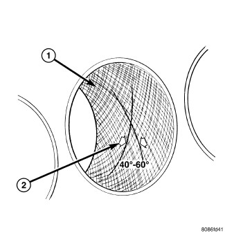
- Honing should be done by moving the hone up and down fast enough to get a crosshatch pattern. The hone marks should INTERSECT at 50° to 60° for proper seating of rings.
- A controlled hone motor speed between 200 and 300 RPM is necessary to obtain the proper crosshatch angle (1). The number of up and down strokes per minute can be regulated to get the desired 50° to 60° angle (2). Faster up and down strokes increase the crosshatch angle.
-
After honing, it is necessary that the block be cleaned to remove all traces of abrasive. Use a brush to wash parts with a solution of hot water and detergent. Dry parts thoroughly. Use a clean, white, lint-free cloth to check that the bore is clean. Oil the bores after cleaning to prevent rusting.
INSPECTION
INSPECTION

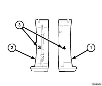 |
- Wipe the main bearing inserts (1 and 2) clean.
- Inspect the inserts for abnormal wear patterns, scoring, grooving, fatigue, pitting and for metal or other foreign material imbedded in the lining.
- Inspect the back of the inserts for fractures, scrapes, or irregular wear patterns.
- Inspect the insert locking tabs for damage.
- Inspect the crankshaft thrust washers for scoring, scratches, wear or blueing.
- Replace any bearing that shows abnormal wear (Refer to 09 - Engine/Engine Block/BEARING(S) , Crankshaft - Standard Procedure)
- Inspect the main bearing bores for signs of scoring, nicks and burrs.
-
If the cylinder block main bearing bores show damage the engine block must be replaced.
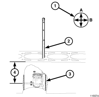
- Use Cylinder Indicator C-119 (2) to correctly measure the inside diameter of the cylinder bore (3). A cylinder bore gauge capable of reading in 0.003 mm (0.0001 in.) INCREMENTS is required. If a bore gauge is not available, do not use an inside micrometer.
- Measure the inside diameter of the cylinder bore at three levels below the top of the bore (4). Start at the top of the bore, perpendicular (across or at 90 degrees) to the axis of the crankshaft at point A (1).
- Repeat the measurement near the middle of the bore, then repeat the measurement near the bottom of the bore.
- Determine taper by subtracting the smaller diameter from the larger diameter.
- Rotate measuring device 90° to point B (1) and repeat the three measurements. Verify that the maximum taper is within specifications (Refer to 09 - Engine - Specifications) .
- Determine out-of-roundness by comparing the difference between A and B at each of the three levels. Verify that the maximum out of round is within specifications (Refer to 09 - Engine - Specifications) .
- If cylinder bore taper and out-of-roundness are within specification, the cylinder bore can be honed (Refer to 09 - Engine/Engine Block - Standard Procedure) . If the cylinder bore taper or out-of-round condition exceeds the maximum limits, the cylinder block must be replaced.
| NOTE: |
A slight amount of taper always exists in the cylinder bore after the engine has been in use for a period of time. |