Valve Timing
- DESCRIPTION
- OPERATION
- RESETTING LEFT CAM CHAIN TENSIONER
- MEASURING TIMING CHAIN WEAR
- ENGINE TIMING VERIFICATION
DESCRIPTION
DESCRIPTION
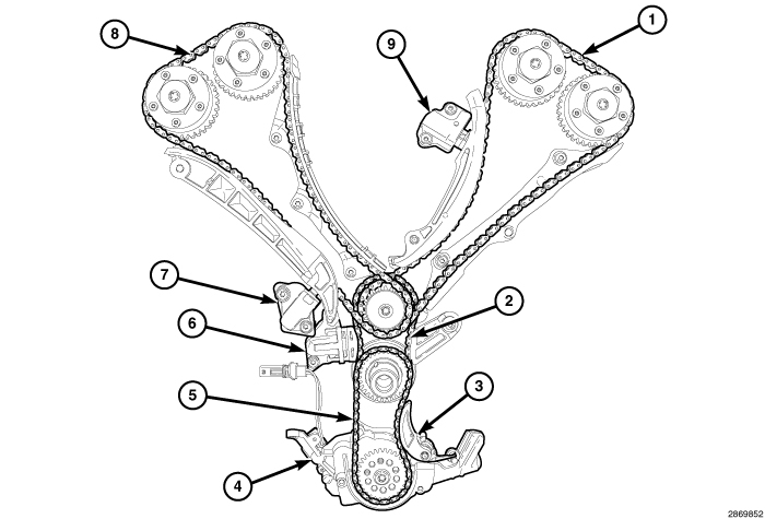 |
The timing drive uses four silent chains. The silent chain link design improves sprocket engagement and reduces noise, vibration and harshness (NVH). One chain (5) drives the oil pump (4) and three chains drive the camshafts in a two stage design. The left secondary camshaft chain (1) uses an oil pressure controlled chain tensioner (9) with a ratcheting device. The right secondary camshaft chain (8) uses an oil pressure controlled tensioner (7) without a ratchet. The primary chain (2) also uses an oil pressure controlled tensioner (6) without a ratchet. A spring loaded tensioner (3) takes up the slack in the oil pump chain (5). The chain guides and tensioner arms are made of glass filled nylon with nylon wear faces.
OPERATION
OPERATION
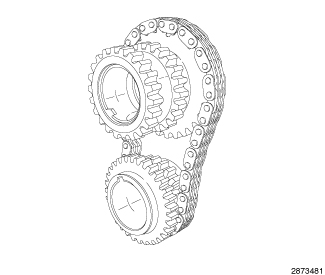 |
The primary timing chain is a silent type. The primary chain drives the 28 tooth idler sprocket directly from a 21 tooth crankshaft sprocket. This results in a 75% speed reduction to the idler sprocket. The idler sprocket assembly connects the primary chain drive and the secondary chain drive. The idler sprocket assembly consists of two integral 22 tooth sprockets a 28 tooth sprocket. The idler sprocket assembly spins on a stationary idler shaft. The idler shaft is a light press-fit into the cylinder block. A large washer on the idler shaft bolt and the rear flange of the idler shaft are used to control sprocket thrust movement. Pressurized oil is routed through the center of the idler shaft to provide lubrication for the bushings used in the idler sprocket assembly. Primary chain motion is controlled by a hydraulic oil damped tensioner and a fixed guide. The tensioner and the guide both use nylon plastic wear faces for low friction and long wear. The primary chain receives oil splash lubrication.
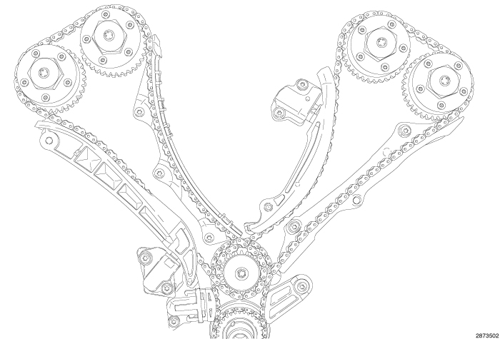 |
There are two identical secondary drive chains, both are silent type, one to drive the camshafts in each double overhead cam (DOHC) cylinder head. The secondary chains drive the 33 tooth camshaft sprockets directly from the 22 tooth idler sprockets. This speed reduction combined with the crankshaft to idler sprocket speed reduction produces the required 2:1 camshaft drive ratio. A fixed chain guide and a hydraulic oil damped tensioner are used to maintain tension in each secondary chain system. The left hydraulic secondary chain tensioner is fed from the main oil gallery through the cylinder head. The right hydraulic secondary chain tensioner is fed from the number one main bearing journal. Each tensioner incorporates a controlled leak path through a device known as a vent disc located in the nose of the piston to manage chain loads. Only the left tensioner has a mechanical ratchet system that limits chain slack if the tensioner piston bleeds down after engine shut down. The tensioner arms and guides also utilize nylon wear faces for low friction and long wear. The two secondary timing chains are lubricated by holes in the oil controlled tensioners that spray oil through an opening in the tensioner arms. The holes are protected from clogging by a fine mesh screen which is located on the back of the hydraulic tensioners.
RESETTING LEFT CAM CHAIN TENSIONER
RESETTING LEFT CAM CHAIN TENSIONER
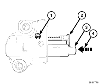 |
The left side can chain tensioner used on the 3.6L engine is equipped with a ratchet. The ratchet consists of a rack (2) and a pawl (1). In use, the rack (2) extends with the piston (3) from the tensioner body. The pawl (1) will not allow the rack (2) to retract back into the tensioner body. In order to reset the tensioner, the pawl (1) must be disengaged from the rack (2) so that the piston (3) and rack (2) can be pushed back (4) into the tensioner body.
 |
WITH ENGINE TIMING COVER REMOVED
| NOTE: |
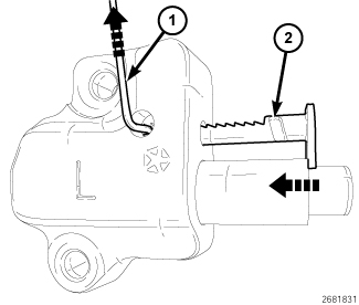
The slot (2) in the rack provides an anchor point for a pin that holds the rack in the retracted position. |
- Using a suitable tool, such as an allen wrench (1), lift the pawl off of the rack.
-
While holding the pawl off of the rack, push the rack and the piston into the tensioner body.
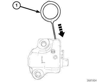
-
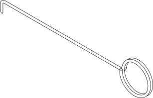
When the slot is aligned with the hole in the tensioner body, insert Tensioner Pin 8514 (1) to hold the rack and piston in the retracted position.
 |
WITH ENGINE TIMING COVER INSTALLED
| NOTE: |
Graphic shows timing cover removed for clarity. |
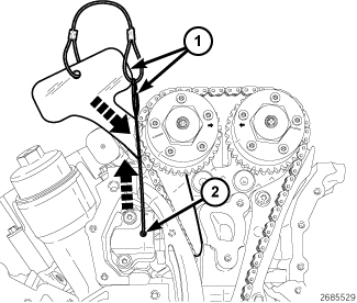
-
Using
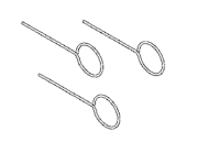
Pin 10200-3 (2), lift the pawl off of the rack (3).
-
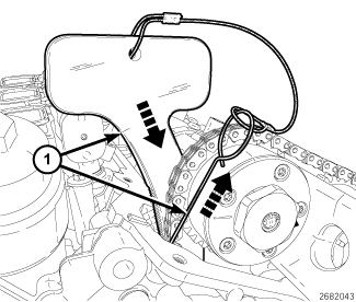
While holding the pawl off of the rack, push
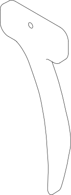
Holder, Timing Chain, Left Side 10200-1 (1) into place between the cylinder head and the cam chain guide to force the rack and piston back into the tensioner body. The holder must remain in place during service to keep the rack and piston in the retracted position.
MEASURING TIMING CHAIN WEAR
MEASURING TIMING CHAIN WEAR
 |
- Remove the engine timing chain cover (Refer to 09 - Engine/Valve Timing/COVER(S) , Engine Timing - Removal).
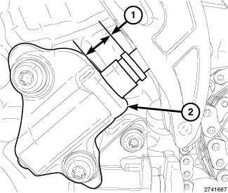
- To determine if the timing chains are worn, rotate the crankshaft clockwise until maximum tensioner piston extension (1) is obtained on the RH cam chain tensioner (2). Measure the distance between the secondary timing chain tensioner housing and the step ledge on the tensioner piston (1). Piston extension (1) must be less than 16 mm (0.630 in.).
-
Piston extension greater than 16 mm (0.630 in.) indicates that all timing chains are worn and require replacement (Refer to 09 - Engine/Valve Timing/CHAIN and SPROCKETS, Timing - Removal)
.
ENGINE TIMING VERIFICATION
ENGINE TIMING VERIFICATION
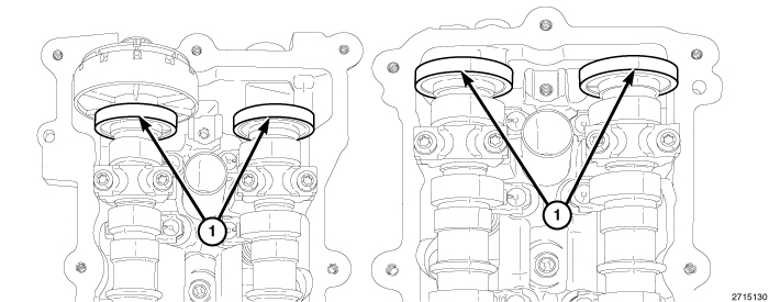 |
The magnetic timing wheels (1)
must not come in contact with magnets (pickup tools, trays, etc.)
or any other strong magnetic field. This will destroy the timing wheels
ability to correctly relay camshaft position to the camshaft position
sensor.
CAUTION:
 |
Correct timing is critical for the NON free-wheeling designed, 3.6L engine. Engine timing can be verified by using the following procedures:
- Remove the upper intake manifold and both cylinder head covers (Refer to 09 - Engine/Cylinder Head/COVER(S) , Cylinder Head - Removal)
-
Remove the spark plugs (Refer to 08 - Electrical/8I - Ignition Control/SPARK PLUG - Removal)
.
CAUTION: When aligning timing marks, always rotate engine by turning the crankshaft. Failure to do so will result in valve and/or piston damage.
-
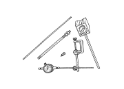
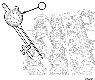
Mount Dial Indicator Set C-3339A (1) to a stationary point on the engine, such as the cylinder head cover mounting surface. Position the indicator probe into the number one cylinder, rotate the crankshaft clockwise (as viewed from the front) to place the number one piston at top-dead-center on the exhaust stroke and set the indicator dial to ZERO.
-
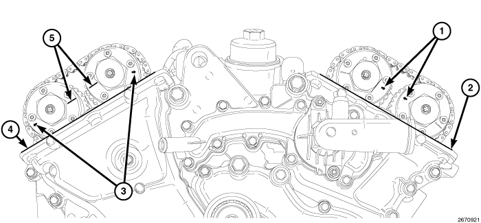
While maintaining this alignment, verify that the ARROWS (1) on the left side cam phasers point toward each other and are parallel to the cylinder head cover mounting surface (2) and that the right side cam phaser ARROWS (3) point away from each other and the SCRIBE LINES (5) are parallel to the cylinder head cover mounting surface (4).
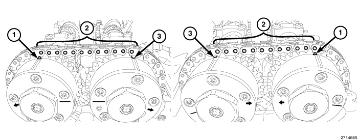
NOTE: The phaser markings (1 and 3) could align with either an external or internal chain link. Either alignment is acceptable as long as there are twelve chain pins between the markings.
- There should be twelve chain pins (2) BETWEEN the exhaust cam phaser triangle marking (1) and the intake cam phaser circle marking (3) as viewed from either the front or rear of the cam phasers.
-
If the engine timing is not correct, proceed to Timing Chain and Sprockets for service procedures (Refer to 09 - Engine/Valve Timing/CHAIN and SPROCKETS, Timing - Removal)