23 - Body
- WARNINGS
- USE OF HEAT DURING REPAIR
- DESCRIPTION
- GENERAL WATER LEAKS
- WATER LEAKS
- WIND NOISE
- BUZZ, SQUEAKS AND RATTLES
- HEAT STAKING
- PLASTIC BODY PANEL REPAIR
- BODY LUBRICATION
- SPECIFICATIONS
- SPECIAL TOOLS
WARNINGS
WARNINGS
Use an Occupational Safety and Health Administration (OSHA) approved breathing filter, when spraying paint or solvents in a confined area. Failure to follow these instructions may result in possible serious or fatal injury.
WARNING:
Restraint Warnings
To avoid potential physical injury, or damage to sensitive electronic circuits and systems, always disconnect and isolate the battery negative (ground) cable and the positive cable, then ground the positive cable to discharge the ORC capacitor before performing any welding operations on the vehicle. Failure to take the proper precautions could result in accidental airbag deployment, possible damage to the Supplemental Restraint System (SRS) circuits and components, and possible damage to other electronic circuits and components. Whenever a welding process is being performed within 30 cm (12 in) of an electronic module/harness, then that module/harness should be relocated out of the way, or disconnected. Always protect against component or vehicle damage from weld spatter by using weld blankets and screens. Failure to follow these instructions may result in serious or fatal injury.
WARNING:
To avoid serious or fatal injury on vehicles equipped with the Supplemental Restraint System (SRS), never attempt to repair the electrically conductive circuits or wiring components related to the SRS for which there is no MOPAR wiring repair kit. It is important to use ONLY the recommended splicing kit and procedure. For applicable and available MOPAR wiring repair kits, please visit the MOPAR Connector Web Site at the following address on the internet: (http://dto.vftis.com/mopar/disclaimer.asp). Inappropriate repairs can compromise the conductivity and current carrying capacity of those critical electrical circuits, which may cause SRS components not to deploy when required, or to deploy when not required. Only minor cuts or abrasions of wire and terminal insulation where the conductive material has not been damaged, or connector insulators where the integrity of the latching and locking mechanisms have not been compromised may be repaired using appropriate methods.
WARNING:
To avoid serious or fatal injury during and following any seat belt or child restraint anchor service, carefully inspect all seat belts, buckles, mounting hardware, retractors, tether straps, and anchors for proper installation, operation, or damage. Replace any belt that is cut, frayed, or torn. Straighten any belt that is twisted. Tighten any loose fasteners. Replace any belt that has a damaged or ineffective buckle or retractor. Replace any belt that has a bent or damaged latch plate or anchor plate. Replace any child restraint anchor or the unit to which the anchor is integral that has been bent or damaged. Never attempt to repair a seat belt or child restraint component. Always replace damaged or ineffective seat belt and child restraint components with the correct, new and unused replacement parts listed in the Chrysler Mopar® Parts Catalog. Failure to follow these instructions may result in possible serious or fatal injury.
WARNING:
To avoid serious or fatal injury on vehicles equipped with side curtain airbags, disable the Supplemental Restraint System (SRS) before attempting any Occupant Restraint Controller (ORC) diagnosis or service. The ORC contains a rollover sensor, which enables the system to deploy the side curtain airbags in the event of a vehicle rollover event. If an ORC is accidentally rolled during service while still connected to battery power, the side curtain airbags will deploy. Disconnect and isolate the battery negative (ground) cable, then wait two minutes for the system capacitor to discharge before performing further diagnosis or service. This is the only sure way to disable the SRS. Failure to take the proper precautions could result in accidental airbag deployment.
WARNING:
To avoid serious or fatal injury on vehicles equipped with airbags, disable the Supplemental Restraint System (SRS) before attempting any steering wheel, steering column, airbag, Occupant Classification System (OCS), seat belt tensioner, impact sensor or instrument panel component diagnosis or service. Disconnect and isolate the battery negative (ground) cable, then wait two minutes for the system capacitor to discharge before performing further diagnosis or service. This is the only sure way to disable the SRS. Failure to follow these instructions may result in accidental airbag deployment.
WARNING:
To avoid potential physical injury or damage to sensitive electronic circuits and systems, always disconnect and isolate the battery negative (ground) cable and the positive cable, then ground the positive cable to discharge the Occupant Restraint Controller (ORC) capacitor before performing any welding operations on the vehicle. Failure to take the proper precautions could result in accidental airbag deployment, possible damage to the Supplemental Restraint System (SRS) circuits and components, and possible damage to other electronic circuits and components. Whenever a welding process is being performed within 12 inches (30 centimeters) of an electronic module or wiring harness, then that module or harness should be relocated out of the way, or disconnected. Always protect against component or vehicle damage from weld spatter by using weld blankets and screens.
WARNING:
To avoid serious or fatal injury, do not attempt to dismantle an airbag unit or tamper with its inflator. Do not puncture, incinerate or bring into contact with electricity. Do not store at temperatures exceeding 93° C (200° F). An airbag inflator unit may contain sodium azide and potassium nitrate. These materials are poisonous and extremely flammable. Contact with acid, water, or heavy metals may produce harmful and irritating gases (sodium hydroxide is formed in the presence of moisture) or combustible compounds. An airbag inflator unit may also contain a gas canister pressurized to over 17.24 kPa (2500 psi). Failure to follow these instructions may result in possible serious or fatal injury.
WARNING:
To avoid serious or fatal injury when handling a seat belt tensioner retractor. Exercise proper care to keep fingers out from under the retractor cover and away from the seat belt webbing where it exits from the retractor cover. Failure to follow these instructions may result in possible serious or fatal injury.
WARNING:
To avoid serious or fatal injury, replace all Supplemental Restraint System (SRS) components only with parts specified in the Chrysler Mopar® Parts Catalog. Substitute parts may appear interchangeable, but internal differences may result in inferior occupant protection.
WARNING:
To avoid serious or fatal injury, the fasteners, screws, and bolts originally used for the Supplemental Restraint System (SRS) components must never be replaced with any substitutes. These fasteners have special coatings and are specifically designed for the SRS. Anytime a new fastener is needed, replace it with the correct fasteners provided in the service package or specified in the Chrysler Mopar® Parts Catalog.
WARNING:
To avoid serious or fatal injury when a steering column has an airbag unit attached, never place the column on the floor or any other surface with the steering wheel or airbag unit face down. Failure to follow these instructions may result in possible serious or fatal injury.
WARNING:
USE OF HEAT DURING REPAIR
USE OF HEAT DURING REPAIR
DESCRIPTION
DESCRIPTION
Throughout this group, references to the Chrysler LLC vehicle family identification code are used when describing a procedure that is unique to that vehicle. Refer to Introduction Group of this manual for detailed information on vehicle identification. If a procedure is common to all vehicles covered in this manual, no reference will be made to a vehicle family code.
GENERAL WATER LEAKS
GENERAL WATER LEAKS
Water leaks can be caused by poor sealing, improper body component alignment, body seam porosity, missing plugs, or blocked drain holes. Centrifugal and gravitational force can cause water to drip from a location away from the actual leak point, making leak detection difficult. All body sealing points should be water tight in normal wet-driving conditions. Water flowing downward from the front of the vehicle should not enter the passenger or luggage compartment. Moving sealing surfaces will not always seal water tight under all conditions. At times, side glass or door seals will allow water to enter the passenger compartment during high pressure washing or hard driving rain (severe) conditions. Overcompensating on door or glass adjustments to stop a water leak that occurs under severe conditions can cause premature seal wear and excessive closing or latching effort. After completing a repair, water test vehicle to verify leak has stopped before returning vehicle to use.
WATER LEAKING DIAGNOSIS:
 |
WATER LEAK BEST PRACTICES:
 |
WATER DRIPPING:
 |
VISUAL INSPECTION BEFORE WATER LEAK TESTS
Verify that floor and body plugs are in place, body drains are clear, and body components are properly aligned and sealed. If component alignment or sealing is necessary, refer to the appropriate section of this group for proper procedures.
WATER LEAK TESTS
Do not use electric shop lights
or tools in water test area. Personal injury can result.
WARNING:
When the conditions causing a water leak have been determined, simulate the conditions as closely as possible.
- If a leak occurs with the vehicle parked in a steady light rain, flood the leak area with an open-ended garden hose.
- If a leak occurs while driving at highway speeds in a steady rain, test the leak area with a reasonable velocity stream or fan spray of water. Direct the spray in a direction comparable to actual conditions.
- If a leak occurs when the vehicle is parked on an incline, hoist the end or side of the vehicle to simulate this condition. This method can be used when the leak occurs when the vehicle accelerates, stops or turns. If the leak occurs on acceleration, hoist the front of the vehicle. If the leak occurs when braking, hoist the back of the vehicle. If the leak occurs on left turns, hoist the left side of the vehicle. If the leak occurs on right turns, hoist the right side of the vehicle. For hoisting recommendations (Refer to 04 - Vehicle Quick Reference/Hoisting - Standard Procedure) .
WATER LEAK DETECTION
To detect a water leak point-of-entry, do a water test and watch for water tracks or droplets forming on the inside of the vehicle. If necessary, remove interior trim covers or panels to gain visual access to the leak area. If the hose cannot be positioned without being held, have someone help do the water test.
Some water leaks must be tested for a considerable length of time to become apparent. When a leak appears, find the highest point of the water track or drop. The highest point usually will show the point of entry. After leak point has been found, repair the leak and water test to verify that the leak has stopped.
Locating the entry point of water that is leaking into a cavity between panels can be difficult. The trapped water may splash or run from the cavity, often at a distance from the entry point. Most water leaks of this type become apparent after accelerating, stopping, turning, or when on an incline.
MIRROR INSPECTION METHOD
When a leak point area is visually obstructed, use a suitable mirror to gain visual access. A mirror can also be used to deflect light to a limited-access area to assist in locating a leak point.
BRIGHT LIGHT LEAK TEST METHOD
Some water leaks in the luggage compartment can be detected without water testing. Position the vehicle in a brightly lit area. From inside the darkened luggage compartment inspect around seals and body seams. If necessary, have a helper direct a drop light over the suspected leak areas around the luggage compartment. If light is visible through a normally sealed location, water could enter through the opening.
PRESSURIZED LEAK TEST METHOD
When a water leak into the passenger compartment cannot be detected by water testing, pressurize the passenger compartment and soap test exterior of the vehicle. To pressurize the passenger compartment, close all doors and windows, start engine, and set heater control to high blower in HEAT position. If engine can not be started, connect a charger to the battery to ensure adequate voltage to the blower. With interior pressurized, apply dish detergent solution to suspected leak area on the exterior of the vehicle. Apply detergent solution with spray device or soft bristle brush. If soap bubbles occur at a body seam, joint, seal or gasket, the leak entry point could be at that location.
WATER LEAKS
WATER LEAKS
| NOTE: |
READ THE FOLLOWING INFORMATION FIRST |
- This manual applies to all Jeep models: 2/4 door & Hard/Soft Top.
- Before testing the vehicle, perform a review of the top system. Make sure all the latches are engaged, none of the top seals are puckered or distorted, the door seals are installed correctly, the tops are not out of alignment, etc..
- Each leak area can have multiple root causes, as noted in the diagnosis chart. It is important to water test each repair before starting the next.
- If a leak cannot be reproduced, it is due to the period of time the vehicle is under wet conditions. Some leaks may take hours before leaking.
- When the door is open, there is water run off from the roof that can soak the carpet. Be sure to explain to the customer that this cannot be fixed. This is an unfortunate condition with this type of vehicle, similar to convertibles.
- If a leak cannot be reproduced, apply all the repairs as noted in the diagnosis chart.
- It is important to understand where the leak ENDS up when diagnosing the vehicle. Where the leak ends up, does not always explain where the leak originates. Refer to the diagnosis chart when determining which repairs to perform.
- This repair procedure does NOT cover every possible water leak on the Jeep Wrangler. The issues identified in this document are the severe leaks that may occur in the field.
- If a hose is required, place on the top of the vehicle facing forward making sure water is getting to all areas. Do NOT directly spray in the area of question. This can create a “false” leak that cannot be fixed.
- Generally, a car wash is the preferred method to diagnose a vehicle.
- The content identifies the severe areas of water leaks, the critical characteristics of each area and how to repair them.
| NOTE: |
Several repairs require the use of a water leak repair foam kit, available through Mopar Parts |
Diagnosis Chart -
|
Water Leak Conditions |
|||
|---|---|---|---|
|
Water is on door trim panel or Instrument Panel at A-pillar |
Water is on center of Instrument Panel / Shifter |
Water at Rear Hard Top Panel / B-pillar |
Water is on front carpet |
Repair Procedure for Windshield Header Seal
This repair procedure is applicable when water is evident on the:
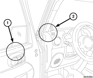 |
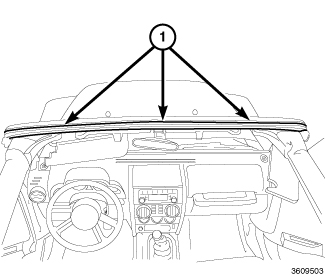 |
-
Remove Header Seal
(1).
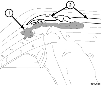
NOTE: A rubber wheel bit may be used to aid in residue removal
- Remove all butyl (1) and tape residue (2).
- Clean surface with general adhesive cleaner.
-
Alcohol wipe entire
surface and allow to dry.
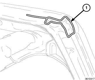
NOTE: This operation is only applicable for vehicles built before 6/1/2008. Vehicles built after this date, should already have sealer present in this area
-
Install 4mm butyl (1)
in a pattern, as shown.
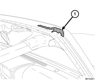
-
Fill in the center
with butyl (1) and make certain to fill in all holes, wrinkles and
step offs to allow for a smooth surface to bond the tape / butyl to
the new seal.
NOTE: Excessive amount of butyl (1) can cause transition voids/leaks. Make sure to smooth out butyl (1)
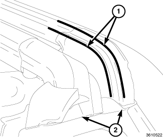
- Locate and install the new seal.
-
Line seal up at end
points (2) on both the left and right side of header.
CAUTION: THIS STEP IS CRITICAL, if not done correctly leak will return
NOTE: It is also critical to pressurize the area at the ends of the seals as indicated in corner areas (1)
NOTE: A small roller or firm finger pressure should be used to be certain the tape is adhered completely from side to side
- Remove release tape and pressurize seal firmly in contact with header sheet metal to smooth out adhesive tape and butyl, starting at the ends and working toward the center.
Repair Procedure for Door Fit and Primary Seal
This repair procedure is applicable when water is evident on the:
|
 |
-
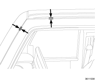
Measure door gaps.
The specifications
are as follows:
If the door fit is
not to spec proceed to Step 2. If door is within specs proceed to
step 3.
NOTE: When adjusting the door the seal must always be replaced
-
Adjust the door gap
and flushness as described. (Refer to 23 - Body/Door - Front/DOOR - Adjustments)
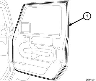
- Inspect door seal (1) for folds and tears.
-
If the door was adjusted
or flaws have been located in the seal, replace door seal (1).
Repair Procedure for A-pillar Mucket and Foam
This repair procedure is applicable when water is evident on the:
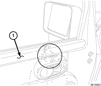 |
Header Mucket-
| NOTE: |
This issue / repair applies to both hard and soft top vehicles |
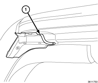 Bad Header Mucket |
- Inspect the header seal mucket for the seal being rolled under (1) the freedom panel or side rail.
-
If the seal is folded under (1), remove the freedom panel or side rail and reinstall making sure not to distort the mucket.
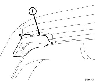 Good Header Mucket |
The header seal mucket (1) installed correctly, will appear as this -
A-pillar Foam
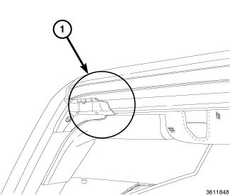 Bad (Missing Foam Seal) |
| NOTE: |
This issue/repair applies to both hard and soft top vehicles |
- Inspect the freedom panel or side rail for damaged / missing foam.
-
If the foam is damaged or missing (1), replace the foam using the foam kit available through Mopar Parts.
The foam seal installed correctly, will appear as this -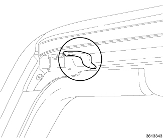
Good Foam Seal
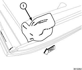
NOTE: Right side panel shown, Left side typical
NOTE: The foam installation is similar for the soft top rail
-
Install the foam (1) to the freedom panel as shown.
Repair Procedures for Freedom Panel Seals
These repair procedures are applicable when water is evident on the:
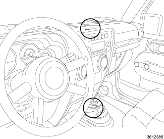 |
Right Hand Freedom Panel
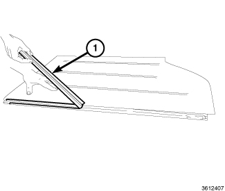 |
-
Remove seal (1) on right side panel.
NOTE: A rubber wheel bit can be used to aid in the removal of tape and butyl residue
-
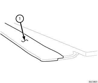
Remove tape residue (2) and butyl residue (1) from panel.
- Clean seal surface (1) with general purpose adhesive cleaner and allow to dry completely.
-
Wipe seal surface (1) with alcohol and allow to dry completely.
-
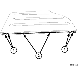
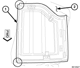
Place right hand freedom panel (1) upside down on a covered surface (2) to prevent scratching.
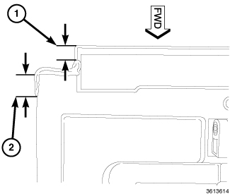
1 = 20 mm
2 = 15 mm
-
Apply 4 mm diameter butyl to Rear Notch, as shown.
NOTE: Follow groove between panels and push butyl firmly in place
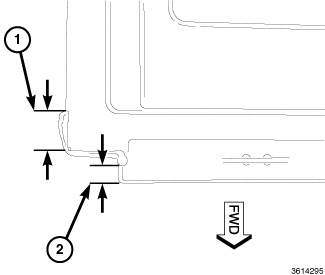
1 = 20 mm
2 = 15 mm
-
Apply 4 mm diameter Butyl to Front Notch, as shown.
NOTE: Follow groove between panels and push butyl firmly in place
NOTE: Keep freedom panel upside down for the initial installation of the seal
NOTE: Secure the end molds first, then finish with the middle of the seal
-
Remove tape liner from the new seal.
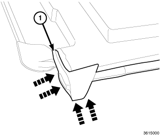
Rear Mold
- Align REAR edge of NEW seal (1) to Right Freedom Panel Notch.
-
Compress butyl by installing seal in direction of arrows.
NOTE: No gap between installed seal and outer edge of freedom panels
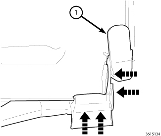
- Align FRONT edge of New seal Right Freedom Panel Notch.
-
Compress butyl by installing seal in direction of arrows.
NOTE: No gap between installed seal and outer edge of freedom panels
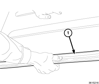
-
Flip panel back over to complete the seal installation.
NOTE: A small roller or firm finger pressure should be used to be certain the seal tape is adhered from front to rear, THIS STEP IS CRITICAL
-
Locate seal cross car against the middle rib in the freedom panel and pressurize starting at the ends and working toward the center.
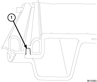
NOTE: This figure is for reference only. Panel is cross cut to show locator rib (1) in the panel
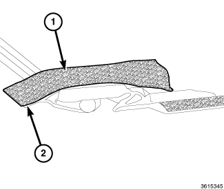
Front of panel
-
On the front of the panel install GREY 30 X 75 mm Foam (1), from the Foam Kit. Locate the foam along trim lines of flame tip (2).
NOTE: Make sure foam covers butyl completely
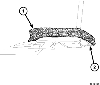
Rear of panel
- On the rear of the panel, install BLACK 30 X 75 mm foam (1), from the Foam Kit. Locate the foam along trim lines of flame tip (2).
| NOTE: |
Make sure foam covers butyl completely |
LEFT HAND FREEDOM PANEL
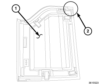 |
-
Place Left hand freedom panel (1) upside down on a covered surface to prevent scratching.
NOTE: The following steps will be applied to the Rear corner (2) of the left side freedom panel (1)
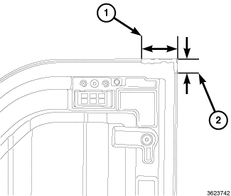
-
Add 4mm diameter butyl, to rear inboard corner groove, as shown.
NOTE: Push butyl firmly into groove between panels until FLUSH
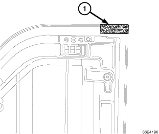
NOTE: Make sure foam covers butyl completely
-
Add 30 X 75 mm Black Foam from the Foam Kit to cover butyl.
Repair Procedures for Freedom Panel Latches
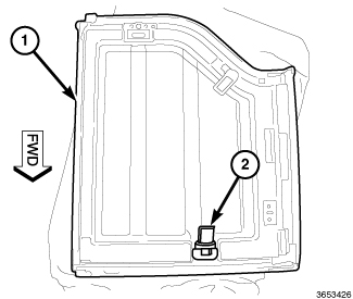 |
| NOTE: |
This applies to both Left and Right Freedom panels (1) |
-
If the vehicle build date is prior to 12/07/07, replace the front latches (2) with the superseded part as found in Mopar Parts.
Repair Procedure for Hard Top Seal
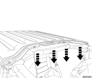 |
This repair procedure is applicable when water is evident on the:
| NOTE: |
Water that enters anywhere
along the hard top seal can travel over to the B-pillar and leak from
the hard top |
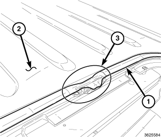 |
-
Inspect for any inconsistency
(3) or deformation between the seal (1) and hard top (2).
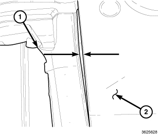
-
Inspect for any gaps
between the seal (1) and hard top (2) edge.
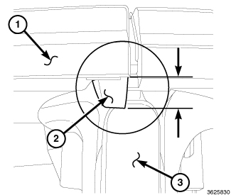
Bad Gap
-
Inspect the end molds
for poor installation.
Hard Top Seal (2) protrudes too far
downward from the Hard Top (1) toward the B-pillar (3). The end mold installed
incorrectly, will appear as this-
Hard Top Seal (2) located between Hard Top (1) to the B-pillar (3). The end mold installed correctly, will appear as this-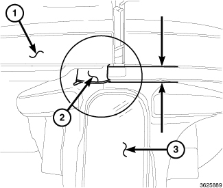
Good Gap
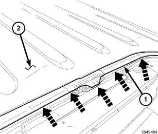
-
Inspect underneath
the seal (1) for any skips with the tape / butyl along the entire
Hard Top (2) mating surface.
Example of tape skip.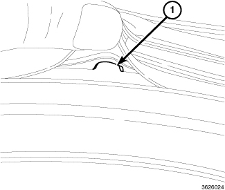
NOTE: If there are multiple skips or the leak cannot be stopped, replace seal
NOTE: A rubber wheel bit can be used to remove the tape
-
Remove all tape / butyl
and clean with alcohol prior to replacement seal installation.
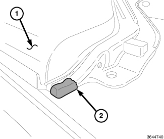
-
Pre-apply butyl (2)
in area shown on hard top (1), prior to installing the seal.
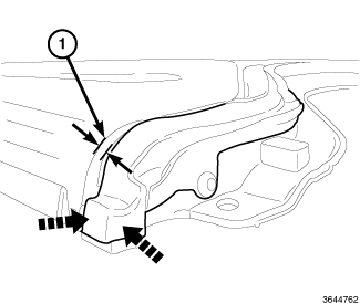
NOTE: It is critical that the end molds are installed correctly and sufficient pressure is applied to wet out the butyl / tape
- Seal should be 2mm under flush (1) from the hard top edge to the seal edge. Measure and adjust as necessary.
-
Apply sufficient pressure
to be certain butyl / tape has bonded thoroughly.
Repair Procedure for B-pillar Mucket
This repair procedure is applicable when water is evident on the:
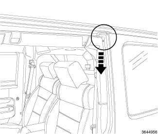 |
| NOTE: |
This repair applies
to 4 door hard top or soft top models |
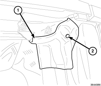 Bad Mucket |
- Inspect the mucket for a rolled under condition (1).
- Inspect the mucket for a missing drain hole (2).
-
If either of these
conditions exist, replace the mucket detail.
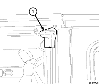
Good Mucket
- Reinstall the panel or side rail making sure not to distort the mucket (1).
The header seal mucket
(1) installed correctly, will appear as this -
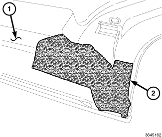 |
- Inspect Freedom Panel for damaged or missing foam.
-
If the foam is damaged
or missing, replace the foam using the Foam Kit available through
Mopar Parts.
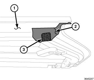
NOTE: This foam (3) is in addition to the foam (2) that is already on the panel (1)
-
Add an additional piece
of foam (3) to the freedom panel as shown This foam can be created
by cutting the 30 x 75mm GREY foam in half, from the Foam Kit.
Repair Procedure for Rear Wheel Flare Hole
This repair procedure is applicable when water is evident on the:
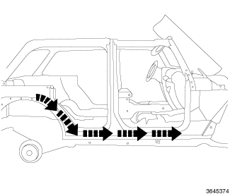 Leak Path |
| NOTE: |
This leak can be diagnosed
by applying a hose to the upper rear flare and inspecting for water
traveling along the floor to the front |
 |
-
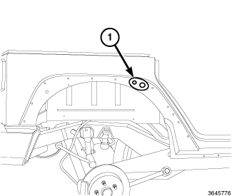
Remove Rear Flare, (Refer to 23 - Body/Exterior/MOLDING
- Removal)
Leak origin location (1) are the holes located under the Rear Flare.
Hole (1) :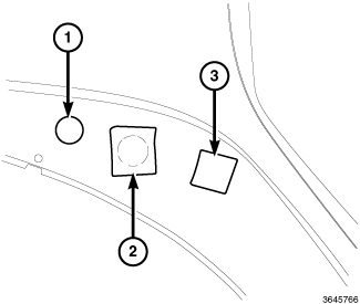
NOTE: Vehicles built prior to 5/28/08 will require this repair
- Inspect the body for missing or misaligned tape over the hole (1).
-
Add/Replace a tape
patch over the hole.
Hole (2) :
NOTE: Vehicles built prior to 5/01/09 will require this repair
- Inspect the body for missing or misaligned tape over the hole (2).
-
Add/Replace a tape
patch over the hole.
Hole (3) :
NOTE: Vehicles built prior to 7/22/08 will require this repair
NOTE: To avoid appearance issues, be certain foam does not extend past the flare trim line
- Cut the BLACK 30 x 75 foam, from the foam kit, in half and apply over this hole.
- Reinstall wheel flare, (Refer to 23 - Body/Exterior/MOLDING - Installation)
Repair Procedure for Cowl Side Panel
This repair procedure is applicable when water is evident on the:
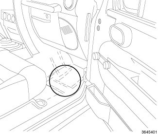 |
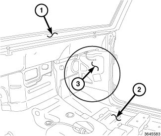 |
|
1 - DASH PANEL 2 - FRONT FLOOR 3 - COWL SIDE PANEL |
Location of the
leak is the Cowl Side Panel (3).
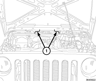 |
| NOTE: |
These leaks can be
diagnosed by applying a water hose in the cowl panel area (1) |
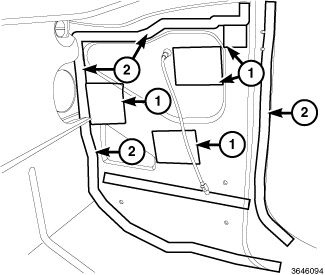 |
Condition (1) : Mastic Patches / Plugs
Condition 2: Seam sealer skips
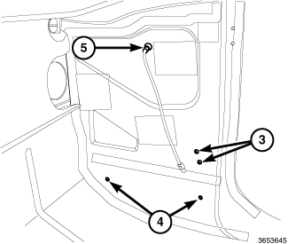
Condition 3: Check strap bracket
Condition 4: Scuff trim foam damaged / missing
Condition 5: Antenna grommet not seated
WIND NOISE
WIND NOISE
Wind noise is the result of most air leaks. Air leaks can be caused by poor sealing, improper body component alignment, body seam porosity, or missing plugs in the engine compartment or door hinge pillar areas. All body sealing points should be airtight in normal driving conditions. Moving sealing surfaces will not always seal airtight under all conditions. At times, side glass or door seals will allow wind noise to be noticed in the passenger compartment during high cross winds. Over compensating door or glass adjustments to stop wind noise that occurs under severe conditions can cause premature seal wear and excessive closing or latching effort. After a repair procedure has been performed, test vehicle to verify noise has stopped before returning vehicle to use.
VISUAL INSPECTION BEFORE TESTS
Verify that floor and body plugs are in place and body components are aligned and sealed. If component alignment or sealing is necessary, refer to the appropriate section of this group for proper procedures.
ROAD TESTING WIND NOISE
- Drive the vehicle to verify the general location of the wind noise.
- Apply 50 mm (2 in.) masking tape in 150 mm (6 in.) lengths along weatherstrips, weld seams or moldings. After each length is applied, drive the vehicle. If noise goes away after a piece of tape is applied, remove tape, locate, and repair defect.
POSSIBLE CAUSE OF WIND NOISE
BUZZ, SQUEAKS AND RATTLES
BUZZ, SQUEAKS AND RATTLES
Buzz, Squeaks and Rattles (BSR's) may be caused by any one or more of the following and may be corrected as indicated:
- Loose fasteners should be tightened to specifications.
- Damaged or missing clips should be replaced.
- Damaged trim panels should be replaced.
- Incorrectly installed trim panels should be reinstalled properly.
Many BSR complaints such as loose trim, can be serviced using various tapes or lubricants. Tapes including foam, flock and anti-squeak, can be used to eliminate noises caused by metal, plastic and vinyl components. Long life lubricants and greases can also be used on a variety of components. Refer to the BUZZ, SQUEAKS AND RATTLES table for materials and usage.
BUZZ, SQUEAKS AND RATTLES
|
ITEM |
FEATURES |
APPLICATIONS |
SERVICE TEMP |
|---|---|---|---|
|
ITCH AND SQUEAK TAPE |
An abrasion resistant material thin enough to conform to most irregular surfaces. Stops most itches and squeaks. |
Between metal and metal, metal and plastic, metal and vinyl, vinyl and plastic. Interior. Examples: Trim panels and bezels. |
-40° to 107° C (-40° to 225° F) |
|
BLACK NYLON FLOCK |
Nylon Flock with an aggressive acrylic adhesive. Provides for cushioning and compression fit, also isolates components. Water-resistant. |
Between metal and metal, metal and plastic, vinyl and plastic. Examples: Pull cups, bezels, clips, ducts, top cover to glass, cowl panel. |
-40° to 82° C (-40° to 180° F) |
|
HIGH DENSITY URETHANE FOAM |
Tear resistant, highly resilient and durable. |
Between metal and metal, metal and plastic. Water-resistant. Examples: I/P, heavy metal rattles, isolating brackets. |
-40° to 82° C (-40° to 180° F) |
|
OPEN CELL FOAM TAPE |
Soft foam conforms to irregular surfaces. |
Wire harness and connector wrap. Examples: Seals, gasket, wiring, heat ducts. |
-40° to 82° C (-40° to 180° F) |
|
CLOSED CELL LOW DENSITY FOAM TAPE |
Soft, conformable. Water-resistant. |
Wherever bulk is needed. Prevents closing flutters and rattles when applied to door watershield. Examples: Door, I/P. |
-40° to 82° C (-40° to 180° F) |
|
NYE® GREASE 880 |
Long life. |
Suspensions. Examples: Strut bushings, sway bars. |
-40° to 200° C (-40° to 390° F) |
|
KRYTOX® OIL |
Long life. Will not dry out or harm plastics or rubber. |
When access is not possible, oil will migrate to condition. Vinyl, rubber, plastic, metal. Examples: Convertible top bushings, pull cups trim panel inserts. |
-34° to 205° C (-30° to 400° F) |
|
KRYTOX® GREASE |
Long life. Will not dry out or harm plastics or rubber. |
Vinyl, rubber, plastic, metal, glass. Examples: Weather-strips, backlite and windshield moldings. |
-34° to 205° C (-30° to 400° F) |
HEAT STAKING
HEAT STAKING
- Remove trim panel.
- Bend or move the trim panel components at the heat staked joints. Observe the heat staked locations and/or component seams for looseness.
-
Heat stake the components.
- If the heat staked or component seam location is loose, hold the two components tightly together and using a soldering gun with a flat tip, melt the material securing the components together. Do not over heat the affected area, damage to the exterior of the trim panel may occur.
- If the heat staked material is broken or missing, use a hot glue gun to apply new material to the area to be repaired. The panels that are being heat staked must be held together while the applying the glue. Once the new material is in place, it may be necessary to use a soldering gun to melt the newly applied material. Do not over heat the affected area, damage to the exterior of the trim panel may occur.
- Allow the repaired area to cool and verify the repair.
- Install trim panel.
PLASTIC BODY PANEL REPAIR
PLASTIC BODY PANEL REPAIR
There are many different types of plastics used in today's automotive environment. We group plastics in three different categories: Rigid, Semi-Rigid, and Flexible. Any of these plastics may require the use of an adhesion promoter for repair. These types of plastic are used extensively on Chrysler LLC vehicles. Always follow repair material manufacturer's plastic identification and repair procedures.
Rigid Plastics:
Examples of rigid plastic use: Fascias, Hoods, Doors, and other Body Panels, which include SMC, ABS, and Polycarbonates.
Semi-Rigid Plastics:
Examples of semi-rigid plastic use: Interior Panels, Under Hood Panels, and other Body Trim Panels.
Flexible Plastics:
Examples of flexible plastic use: Fascias, Body Moldings, and upper and lower Fascia Covers.
Repair Procedure:
The repair procedure for all three categories of plastics is basically the same. The one difference is the material used for the repair. The materials must be specific for each substrate, rigid repair material for rigid plastic repair, semi-rigid repair material for semi-rigid plastic repair and flexible repair material for flexible plastic repair.
Adhesion Promoter/Surface Modifier:
Adhesion Promoters/Surface Modifiers are required for certain plastics. All three categories may have plastics that require the use of adhesion promoter/surface modifiers. Always follow repair material manufacturer's plastic identification and repair procedures.
SAFETY PRECAUTION AND WARNINGS
Failure to follow these instructions
may result in serious or fatal injury.
WARNING:
| NOTE: |
RIGID, SEMI-RIGID, AND FLEXIBLE PLASTIC PARTS TYPES
|
CODE |
FAMILY NAME |
COMMON TRADE NAME |
TYPICAL APPLICATION |
|---|---|---|---|
|
ASA |
ACRYLONITRILE STYRENE ACRYLITE |
LURAN S |
CONSOLES, GRILLES |
|
ABS |
ACRYLONITRILE BUTADIENE STYRENE |
TERLURAN |
"A" PILLARS, CONSOLES, GRILLES |
|
ABS/PC |
ABS/PC ALLOY |
PULSE, PROLOY, BAYBLEND |
DOORS, INSTRUMENT PANELS |
|
ABS/PVC |
ABS/PV ALLOY |
PROLOY, PULSE, LUSTRAN, CYCLOVIN |
DOOR PANELS, GRILLES, TRIM |
|
BMC |
BULK MOLDING COMPOUND |
BMC |
FENDER EXTENSIONS |
|
EMA |
EHTYLENE METHYL ACRYLATE/IONOMER |
SURLYN, EMA, IONOMER |
BUMPER GUARDS, PADS |
|
METTON |
METTON |
METTON |
GRILLES, KICK PANELS, RUNNING BOARDS |
|
MPPO |
MODIFIED POLYPHENYLENE OXIDE |
MPPO |
SPOILER ASSEMBLY |
|
PA |
POLYAMID |
ZYTEL, VYDYNE, PA, MINLON |
FENDERS, QUARTER PANELS |
|
PET |
THERMOPLASTIC POLYESTER |
RYNITE |
TRIM |
|
PBT/PPO |
PBT/PPO ALLOY |
GERMAX |
CLADDINGS |
|
PBTP |
POLYBUTYLENE THEREPTHALATE |
PBT, PBTP, POCAN, VALOX |
WHEEL COVERS, FENDERS, GRILLES |
|
PBTP/EEBC |
POLYBUTYLENE THEREPTHALATE/EEBC ALLOY |
BEXLOY, "M", PBTP/EEBC |
FASCIAS, ROCKER PANEL, MOLDINGS |
|
PC |
POLYCARBONATE |
LEXAN, MERLON, CALIBRE, MAKROLON PC |
TAIL LIGHT LENSES, IP TRIM, VALANCE PANELS |
|
PC/ABS |
PC/ABS ALLOY |
GERMAX, BAY BLENDS, PULSE |
DOORS, INSTRUMENT PANELS |
|
PPO |
POLYPHENYLENE OXIDE |
AZDEL, HOSTALEN, MARLEX, PRFAX, NORYL, GTX, PPO |
INTERIOR TRIM, DOOR PANELS, SPLASH SHIELDS, STEERING COLUMN SHROUD |
|
PPO/PA |
POLYPHENYLENE/POLYAMID |
PPO/PA, GTX 910 |
FENDERS, QUARTER PANELS |
|
PR/FV |
FIBERGLASS REINFORCED PLASTIC |
FIBERGLASS, FV, PR/FV |
BODY PANELS |
|
PS |
POLYSTYRENE |
LUSTREX, STYRON, PS |
DOOR PANELS, DASH PANELS |
|
RTM |
RESIN TRANSFER MOLDING COMPOUND |
RTM |
BODY PANELS |
|
SMC |
SHEET MOLDED COMPOUND |
SMC |
BODY PANELS |
|
TMC |
TRANSFER MOLDING COMPOUND |
TMC |
GRILLES |
|
UP |
UNSATURATED POLYESTER (THERMOSETTING) |
SMC, BMC, TMC, ZMC, IMC, XSMC, UP |
GRILLE OPENING PANEL, LIFTGATES, FLARESIDE FENDERS, FENDER EXTENSIONS |
|
EEBC |
ETHER/ESTER BLOCKED CO-POLYMER |
EEBC |
BUMPERS |
|
EEBC/PBTP |
EEBC/POLYBUTYLENE TEREPTHALATE |
EEBC, PBTP, BEXLOY |
BUMPER, ROCKER PANELS |
|
EMPP |
ETHYLENE MODIFIED POLYPROPYLENE |
EMPP |
BUMPER COVERS |
|
EPDM |
ETHYLENE/PROPROPYLENE DIENE MONOMER |
EPDM, NORDEL, VISTALON |
BUMPERS |
|
EPM |
ETHYLENE/PROPROPYLENE CO-POLYMER |
EPM |
FENDERS |
|
MPU |
FOAM POLYURETHANE |
MPU |
SPOILERS |
|
PE |
POLYETHYLENE |
ALATHON, DYLAN, LUPOLEN, MARLEX |
”? |
|
PP |
POLYPROPYLENE (BLENDS) |
NORYL, AZDEL, MARLOX, DYLON, PRAVEX |
INNER FENDER, SPOILERS, KICK PANELS |
|
PP/EPDM |
PP/EPDM ALLOY |
PP/EPDM |
SPOILERS, GRILLES |
|
PUR |
POLYURETHANE |
COLONELS, PUR, PU |
FASCIAS, BUMPERS |
|
PUR/PC |
PUR/PC ALLOY |
TEXIN |
BUMPERS |
|
PVC |
POLYVINYL CHLORIDE |
APEX, GEON, VINYLITE |
BODY MOLDINGS, WIRE INSULATION, STEERING WHEELS |
|
RIM |
REACTION INJECTED MOLDED POLYURETHANE |
RIM, BAYFLEX |
FRONT FASCIAS, MODULAR WINDOWS |
|
RRIM |
REINFORCED REACTION INJECTED MOLDED |
PUR, RRIM |
FASCIAS, BODY PANELS, BODY TRIMS |
|
TPE |
THERMO POLYETHYLENE |
TPE, HYTREL, BEXLOY-V |
FASCIAS, BUMPERS, CLADDINGS |
|
TPO |
THERMOPOLYOLEFIN |
POLYTROPE, RENFLEX, SANTOPRENE, VISAFLEX, ETA, APEX, TPO, SHIELDS, CLADDINGS |
BUMPERS, END CAPS, TELCAR, RUBBER, STRIPS, SIGHT, INTERIOR B POST |
|
TPP |
THERMO-POLYPROPYLENE |
TPP |
BUMPERS |
|
TPU |
THERMOPOLYURETHANE, POLYESTER |
TPU, HYTREL, TEXIN, ESTANE |
BUMPERS, BODY SIDE, MOLDINGS, FENDERS, FASCIAS |
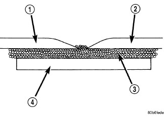
PANEL SECTIONING
 |
|
1 - EXISTING PANEL 2 - NEW PANEL 3 - PANEL ADHESIVE 4 - BONDING STRIP |
If it is required to section a large panel for a plastic repair, it will be necessary to reinforce the panel. To bond two plastic panels together, a reinforcement must overlap both panels. The panels must be “V'd” at a 20 degree angle. The area to be reinforced should be washed, then sanded. Be sure to wipe off any excess soap and water when finished. Lightly sand or abrade the plastic with an abrasive pad or sandpaper. Blow off any dust with compressed air or wipe with a clean dry rag.
When bonding plastic panels, follow repair material manufacturers recommendations. Be sure that enough adhesive has been applied to allow squeeze out and to fill the full bond line. Once the pieces have been brought together, do not move them until the adhesive is cured. The assembly can be held together with clamps, rivets, etc. A faster cure can be obtained by heating with a heat lamp or heat gun. After the parts have been bonded and have had time to cure, rough sand the seam and apply the final adhesive filler to the area being repaired. Smooth the filler with a spreader, wooden tongue depressor, or squeegee. For fine texturing, a small amount of water can be applied to the filler surface while smoothing. The cured filler can be sanded as necessary and, as a final step, cleanup can be done with soapy water. Wipe the surface clean with a dry cloth allowing time for the panel to dry before moving on with the repair.
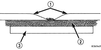
PANEL REINFORCEMENT
 |
|
1 - SOFTENED EDGES 2 - PANEL ADHESIVE 3 - BONDING STRIP |
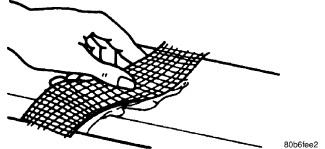
Structural repair procedures for rigid panels with large cracks
and holes will require a reinforcement backing. Reinforcements can
be made with several applications of glass cloth saturated with structural
adhesive. Semi-rigid or flexible repair materials should be used for
semi-rigid or flexible backing reinforcement and open meshed fiberglass
dry wall tape can be used to form a reinforcement. The dry wall tape
allows the resin to penetrate through and make a good bond between
the panel and the adhesive. Structurally, the more dry wall tape used,
the stronger the repair.
 |
|
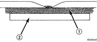
1 - PANEL ADHESIVE 2 - REINFORCEMENT |
Another kind of repair that can be done to repair large cracks
and holes is to use a scrap piece of similar plastic and bond with
structural adhesive. The reinforcement should cover the entire break
and should have a generous amount of overlap on either side of the
cracked or broken area.
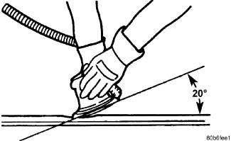 |
When repairing plastic, the damaged area is first “V'd” out, or
beveled. Large bonding areas are desirable when repairing plastic
because small repairs are less likely to hold permanently. Beveling
the area around a crack at a 20° angle will increase the bonding surface
for a repair. It is recommended that sharp edges be avoided because
the joint may show through after the panel is refinished.
 |
- Panel repair for both flexible and rigid panels are basically the same. The primary difference between flexible panel repair and rigid panel repair is in the adhesive materials used.
- The technician should first decide what needs to be done when working on any type of body panel. One should determine if it is possible to return the damage part to its original strength and appearance without exceeding the value of the replacement part.
-
When plastic repairs
are required, it is recommended that the part be left on the vehicle
when ever possible. That will save time, and the panel will remain
stationary during the repair. Misalignment can cause stress in the
repair areas and can result in future failure.
VISUAL INSPECTION
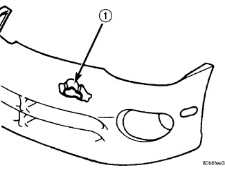 |
Composite materials can mask the severity of an accident. Adhesive bond lines, interior structure of the doors, and steel structures need to be inspected carefully to get a true damage assessment. Close inspection may require partial removal of interior trim or inner panels.
Identify the type of repair: Puncture (1) or Crack - Damage that has penetrated completely through the panel. Damage is confined to one general area; a panel section is not required. However, a backer panel, open fiberglass tape, or matted material must be bonded from behind.
PANEL SURFACE PREPARATION
If a body panel has been punctured, cracked, or crushed, the damaged area must be removed from the panel to achieve a successful repair. All spider web cracks leading away from a damaged area must be stopped or removed. To stop a running crack in a panel, drill a 6 mm (0.250 in.) hole at the end of the crack farthest away from the damage. If spider web cracks can not be stopped, the panel would require replacement. The surfaces around the damaged area should be stripped of paint and freed from wax and oil. Sand surfaces around repair area with 80 -120 grit sandpaper, or equivalent, to assure adhesion of repair materials.
PATCHING PANELS
 |
|
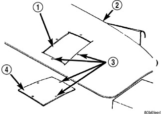
1 - CUTOUT 2 - DAMAGED BODY PANEL 3 - 4 MM (0.160 IN.) HOLES 4 - PATCH CUT TO SIZE |
A panel that has extensive puncture type damage can be repaired by cutting out the damaged material. Use a suitable reciprocating saw or cut off wheel to remove the section of the panel that is damaged. The piece cut out can be used as a template to shape the new patch. It is not necessary to have access to the back of the panel to install a patch. Bevel edges of cutout at 20° to expose a larger bonding area on the outer side. This will allow for an increased reinforcement areas.
PANEL PATCH FABRICATIONS
 |
|
1 - STRUCTURAL ADHESIVE 2 - FIBERGLASS CLOTH OR FIBERGLASS MESH TAPE 3 - WIDTH OF V-GROOVE 4 - WAXED PAPER |
A patch can be fabricated from any rigid fiberglass panel that has comparable contour with the repair area. Lift gates and fenders can be used to supply patch material. If existing material is not available or compatible, a patch can be constructed with adhesive and reinforcement mesh (dry wall tape). Perform the following operation if required:
- Cover waxed paper or plastic with adhesive backed nylon mesh (dry wall tape) larger than the patch required.
- Tape waxed paper or plastic sheet with mesh to a surface that has a compatible contour to the repair area.
- Apply a liberal coat of adhesive over the reinforcement mesh. If necessary apply a second or third coat of adhesive and mesh after first coat has cured. The thickness of the patch should be the same as the repair area.
- After patch has cured, peel waxed paper or plastic from the back of the patch.
-
If desired, a thin film coat of adhesive can be applied to the back of the patch to cover mesh for added strength.
PANEL PATCH INSTALLATION
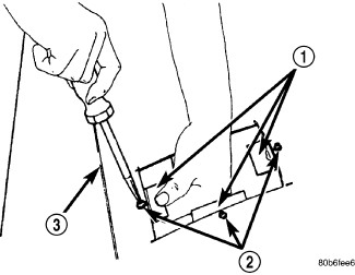 |
|
1 - SUPPORT SQUARES 2 - SCREWS 3 - DAMAGED BODY PANEL |
- Make a paper or cardboard pattern the size and shape of the cutout hole in the panel.
- Trim 3 mm (0.125 in.) from edges of pattern so patch will have a gap between connecting surfaces.
- Using the pattern as a guide, cut the patch to size.
- Cut scrap pieces of patch material into 50 mm (2 in.) squares to use as patch supports to sustain the patch in the cutout.
- Drill 4 mm (0.160 in.) holes 13 mm (0.5 in.) in from edge of cutout hole.
- Drill 4 mm (0.160 in.) holes 13 mm (0.5 in.) away from edge of patch across from holes drilled around cutout.
- Drill 3 mm (0.125 in.) holes in the support squares 13 mm (0.5 in.) from the edge in the center of one side.
- Scuff the backside of the body panel around the cutout hole with a scuff pad or sandpaper.
- Mix enough adhesive to cover one side of all support squares.
- Apply adhesive to cover one side of all support squares.
-
Using number 8 sheet metal screws, secure support squares to back side of body panel with adhesive sandwiched between the panel and squares.
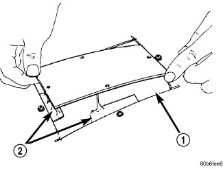
- Position patch in cutout (1) against support squares (2) and adjust patch until the gap is equal along all sides.
-
Drill 3 mm (0.125 in.) holes in the support squares through the pre-drilled holes in the patch.
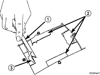
-
Apply a coat of adhesive (3) to the exposed ends of the support squares (2).
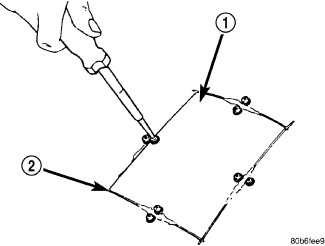
- Install screws to hold the patch (1) to support squares. Tighten screws until patch surface is flush with panel surface.
-
Allow adhesive to cure, and remove all screws.
-
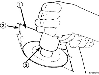
Using a 125 mm (5 in.) 24 grit disc grinder (3), grind a 50 mm (2 in.) to 75 mm (3 in.) wide and 75% -80% deep (original material thickness) path across the gaps (2) around the patch (1). With compressed air, blow dust from around patch.
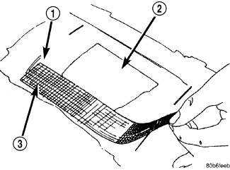
1 - GROUND DOWN AREA
2 - PATCH
3 - MESH
- Apply adhesive backed nylon mesh (dry wall tape) over gaps around patch.
-
Mix enough adhesive to cover the entire patch area.
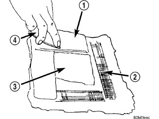
1 - ADHESIVE
2 - MESH
3 - PATCH
4 - SPREADER
-
Apply adhesive over the mesh around patch, and smooth epoxy with a wide spreader to reduce finish grinding. Use two to three layers of mesh and adhesive to create a stronger repair.
PATCHED PANEL SURFACING
After patch panel is installed, the patch area can be finished using the same methods as finishing other types of body panels. If mesh material is exposed in the patched area, grind surface down, and apply a coat of high quality rigid plastic body filler. Prime, block sand, and paint as required.
BODY LUBRICATION
BODY LUBRICATION
All mechanisms and linkages should be lubricated when necessary. This will maintain ease of operation and provide protection against rust and excessive wear. The weatherstrip seals should be lubricated to prolong their life as well as to improve door sealing.
All applicable exterior and interior vehicle operating mechanisms should be inspected and cleaned. Pivot/sliding contact areas on the mechanisms should then be lubricated.
- When necessary, lubricate the operating mechanisms with the specified lubricants.
- Apply silicone lubricant to a cloth and wipe it on door seals to avoid over-spray that can soil passenger's clothing.
- Before applying lubricant, the component should be wiped clean. After lubrication, any excess lubricant should be removed.
- The hood latch, latch release mechanism, latch striker, and safety latch should be lubricated periodically.
- The door lock cylinders should be lubricated twice each year (preferably autumn and spring):
- Spray a small amount of lock cylinder lubricant directly into the lock cylinder.
- Apply a small amount to the key and insert it into the lock cylinder.
- Rotate it to the locked position and then back to the unlocked position several times.
- Remove the key. Wipe the lubricant from it with a clean cloth to avoid soiling of clothing.
|
Component |
Fluid, Lubricant, or Genuine Part |
|---|---|
|
Hinges: |
|
|
Door And Hood |
Mopar® Engine Oil |
|
Liftgate |
Mopar® Multi-Purpose Lube NLGI Grade 2 EP, GC-LB |
|
Latches: |
|
|
Door, Hood/Safety Catch, Liftgate |
Mopar® Multi-Purpose Lube NLG Grade 2 EP, GC-LB |
|
Seat Regulator AND Track |
Mopar® Multi-Purpose Lube NLGI Grade 2 EP, GC-LB |
|
Window System Components |
Mopar® Spray White Lube |
|
Lock Cylinders |
Mopar® Lock Cylinder Lube |
|
Parking Brake Mechanism |
Mopar® Wheel Brg. Grease NLGI Grade 1, GC-LBB |
|
Soft Top |
Mopar® Soft Top Zipper Cleaner AND Lubricant |
SPECIFICATIONS
SPECIFICATIONS
|
Description |
N·m |
Ft. Lbs |
In. Lbs. |
|---|---|---|---|
|
A/C expansion valve nut |
23 |
17 |
— |
|
Backlite hinge bolts |
10 |
— |
90 |
|
Body isolator mounting bolts * |
108 |
80 |
— |
|
Body isolator to body nuts |
54 |
40 |
— |
|
Brake booster bracket nuts |
18 |
13.5 |
— |
|
Center OCS strain gauge stud nut |
45 |
33 |
— |
|
Door carrier plate screws |
10 |
— |
90 |
|
Door hinge pin nut |
8.5 |
— |
75 |
|
Door hinge to body bolts |
24 |
18 |
— |
|
Door hinge to hinge bolts |
26 |
19 |
— |
|
Door latch adjustment screw |
3 |
— |
26.5 |
|
Door latch mounting screws |
8 |
— |
71 |
|
Door latch striker bolts |
26 |
19 |
— |
|
Four door rear seat 40% inner seat back pivot nut |
25 |
18.5 |
— |
|
Four door rear seat center belt buckle bolt |
61 |
45 |
— |
|
Four door rear seat cushion pivot bolts |
25 |
18.5 |
— |
|
Four door rear seat front mounting fasteners |
75 |
55 |
— |
|
Four door rear seat headrest bolts |
8 |
— |
71 |
|
Four door rear seat inner latch floor bolts |
25 |
18.5 |
— |
|
Four door rear seat latch to back frame bolts |
45 |
33 |
— |
|
Four door rear seat outboard latch floor bolts |
25 |
18.5 |
— |
|
Four door rear seat rear mounting bolt |
75 |
55 |
— |
|
Four door rear seat rear mounting nuts |
85 |
62.5 |
— |
|
Four door rear seat cushion pivot bolt |
25 |
18.5 |
— |
|
Four door retractor screw |
55 |
41 |
— |
|
Four door seat cushion pivot bolt |
25 |
18.5 |
— |
|
Front door exterior handle nut |
4.5 |
— |
40 |
|
Front door glass run nut |
10 |
— |
90 |
|
Front door interior handle screw |
8.5 |
— |
75 |
|
Front seat back assembly bolts |
47 |
34.5 |
— |
|
Front seat belt anchor bolt |
40 |
29.5 |
— |
|
Front seat belt buckle bolt |
50 |
37 |
— |
|
Front seat belt turning loop screw |
40 |
29.5 |
— |
|
Front seat mounting bolts |
75 |
55 |
— |
|
Front seat riser nuts |
28 |
21 |
— |
|
Half door latch nut |
4.5 |
— |
40 |
|
Hard top front bolts |
8 |
— |
71 |
|
Hard top side bolts |
8 |
— |
71 |
|
Hood catch bracket nuts |
7 |
— |
62 |
|
Hood catch nuts |
15 |
11 |
— |
|
Hood hinge to body bolts |
24 |
18 |
— |
|
Hood hinge to hood bolts |
26 |
19 |
— |
|
Hood safety catch bolt |
11 |
8 |
97 |
|
Instrument panel center support bracket fasteners |
8 |
6 |
71 |
|
Instrument panel fence line nuts |
12 |
9 |
— |
|
Instrument panel side support bolts |
11 |
8 |
— |
|
Lower fender to sill bolts |
12 |
9 |
— |
|
Manual sifter bolt |
33 |
24.5 |
— |
|
OCS riser nuts |
28 |
21 |
— |
|
Outside rear view mirror bolts |
13 |
10 |
— |
|
Rear door exterior handle nut |
4.5 |
— |
40 |
|
Rear door glass run bolt |
12 |
9 |
— |
|
Rear door glass run nut |
10 |
— |
90 |
|
Rear door interior handle screw |
8.5 |
— |
75 |
|
Rear view mirror set screw |
2 |
— |
18 |
|
Seat side airbag nuts |
7 |
— |
62 |
|
Side step bracket bolts |
24 |
18 |
— |
|
Side step sill nuts |
12 |
9 |
— |
|
Soft top pivot knuckle bolts |
14 |
10 |
— |
|
Speaker pod screws |
10 |
— |
90 |
|
Sport bar cross bar bracket bolts |
19 |
14 |
— |
|
Sport bar front cross bar bracket bolts |
19 |
14 |
— |
|
Sport bar rear bolts |
19 |
14 |
— |
|
Sport bar rear cross bar bracket bolts |
19 |
14 |
— |
|
Sport bar side bar bolts |
19 |
14 |
— |
|
Sport bar side bar to windshield frame bolts |
23 |
17 |
— |
|
Sport bar to B-pillar bolts |
19 |
14 |
— |
|
Steering column opening reinforcement plate bolts |
11 |
8 |
— |
|
Tailgate exterior handle nuts |
4.5 |
— |
40 |
|
Tailgate hinge to body bolts |
26 |
19 |
— |
|
Tailgate hinge to tailgate bolts |
26 |
19 |
— |
|
Tailgate latch screws |
8 |
— |
71 |
|
Tailgate stabilizer insert and cup bolts |
10 |
— |
90 |
|
Tailgate striker bolts |
28 |
21 |
— |
|
Two door rear seat back frame to cushion bolts |
50 |
37 |
— |
|
Two door rear seat back latch bolts |
45 |
33 |
— |
|
Two door rear seat center belt buckle bolt |
55 |
41 |
— |
|
Two door rear seat cushion to back bolts |
50 |
37 |
— |
|
Two door rear seat front latch cushion frame bolts |
45 |
33 |
— |
|
Two door rear seat rear latch nuts |
10 |
— |
90 |
|
Upper fender fasteners |
5 |
— |
44 |
|
Windshield frame hinge to body bolts |
20 |
15 |
— |
|
Windshield frame reinforcement bracket bolts |
20 |
15 |
— |
* Whenever a body isolator bolt
requires servicing or tightening, it is necessary to remove the bolt
and install new thread locker compound to the threads.
CAUTION:
SPECIAL TOOLS
SPECIAL TOOLS
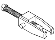 |
C-4333A-1 - Puller, Pulley |
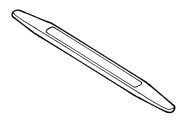 |
C-4755 - Trim Stick Originally Shipped In Kit Number(s) 9299, 9299CC, 9299CC, 9300A-CAN. |
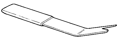 |
C-4829A - Remover, Trim |