Home › 28 - DTC-Based Diagnostics › AMPLIFIER (AMP) › B1473-CHANNEL 4 AUDIO SPEAKER OUTPUT CIRCUIT SHORTED TOGETHERB1473-CHANNEL 4 AUDIO SPEAKER OUTPUT CIRCUIT SHORTED TOGETHER
B1473-CHANNEL 4 AUDIO SPEAKER OUTPUT CIRCUIT SHORTED TOGETHER For a complete wiring diagram, refer to the Wiring Information .
Possible Causes
(X202) RIGHT FRONT SPEAKER (+) CIRCUIT SHORTED TO THE (X292) RIGHT FRONT SPEAKER (-) CIRCUIT
RIGHT FRONT SPEAKER
AMPLIFIER
1.
CHECK FOR AN INTERMITTENT CONDITION
2.
Using the scan tool, record and erase the Amplifier DTCs.
3.
Cycle the ignition switch from on to off, wait five seconds and then back to on.
4.
Turn the Radio on and set the volume to 25.
5.
Adjust the speakers to the front and center.
6.
Using the scan tool, read the active Amplifier DTCs.
Does the scan tool display active: B1473-CHANNEL 4 AUDIO SPEAKER OUTPUT CIRCUIT SHORTED TOGETHER? Yes
No
2.
CHECK THE OPERATION OF THE RIGHT FRONT SPEAKER
1.
Turn the ignition off.
2.
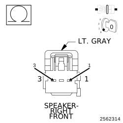
Disconnect the Right Front Speaker harness connector.
3.
Measure the resistance of the speaker between the two terminals.
NOTE:
The graphic shows the connector for reference only. Measure between the speaker terminals
Is the resistance of the speaker less than 1 Ohm? Yes
No
3.
CHECK THE (X202) RIGHT FRONT SPEAKER (+) CIRCUIT, AND THE (X292) RIGHT FRONT SPEAKER (-) CIRCUITS FOR A SHORT TOGETHER
1.
Turn the ignition off.
2.
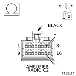
Disconnect the Amplifier C2 harness connector.
3.
Measure the resistance between the (X202) Right Front Speaker (+) circuit, and the (X292) Right Front Speaker (-) circuit.
Is the resistance below 10K Ohms? Yes
No