B1B8F-DRIVER SEAT TRACK POSITION SENSOR CIRCUIT OPEN
B1B8F-DRIVER SEAT TRACK POSITION SENSOR CIRCUIT OPEN
 |
For a complete wiring diagram, refer to the Wiring Information.
Possible Causes
-
When Monitored:
While the CAN bus ignition status is in IGN_RUN and the module is configured for a Seat Track Position Sensor, the Occupant Restraint Controller (ORC) checks the sensor input current ranges.
-
Set Condition:
This DTC may set when the ORC detects that the sensor input current is below 1 mA.
Possible Causes |
|---|
| DRIVER SEAT HARNESS IMPROPERLY ROUTED |
| DRIVER SEAT HARNESS WIRES CHAFED, PIERCED, PINCHED, PARTIALLY BROKEN |
| DRIVER SEAT HARNESS CONNECTOR TERMINALS BROKEN, BENT, PUSHED OUT, SPREAD, CORRODED, CONTAMINATED |
| (R261) DRIVER SEAT POSITION SENSOR SIGNAL CIRCUIT SHORTED TO VOLTAGE |
| (R263) DRIVER SEAT POSITION SENSOR SUPPLY CIRCUIT SHORTED TO VOLTAGE |
| (R261) DRIVER SEAT POSITION SENSOR SIGNAL CIRCUIT SHORTED TO THE (R263) DRIVER SEAT POSITION SENSOR SUPPLY CIRCUIT |
| DRIVER SEAT TRACK POSITION SENSOR |
| OCCUPANT RESTRAINT CONTROLLER (ORC) |
1. CHECK FOR ACTIVE INTERNAL FAULTS, IGNITION FAULTS, AND BATTERY FAULTS IN THE OCCUPANT RESTRAINT CONTROLLER (ORC)
| 1. | With the scan tool, read Occupant Restraint Controller (ORC) DTC. |
Does the scan tool display any active DTC relating to internal faults, ignition faults, or battery faults?
Yes
- (Refer to 28 - DTC-Based Diagnostics/CONTROLLER, Occupant Restraint (ORC) - Diagnosis and Testing) and perform the appropriate diagnostic procedure.
No
- Go To 2
2. VERIFY THAT DTC B1B8F-DRIVER SEAT TRACK POSITION SENSOR CIRCUIT OPEN IS ACTIVE
Does the scan tool display active B1B8F-DRIVER SEAT TRACK POSITION SENSOR CIRCUIT OPEN DTC?
Yes
- Go To 3
No
- Go To 8
3. INSPECT DRIVER SEAT HARNESS WIRES AND CONNECTORS
Turn the ignition off, disconnect
the 12-volt battery and wait two minutes before proceeding. Failure
to follow these instructions may result in possible serious or fatal
injury.
WARNING:
| 1. | Using the wiring diagram/schematic as a guide, inspect the Driver Seat Harness wiring and connectors. Look for chafed, pierced, pinched, or partially broken wires and broken, bent, pushed out, spread, corroded, or contaminated terminals. |
Are any of these conditions present?
Yes
-
NOTE: Do not attempt to repair the Seat Harness. Replace the Seat Harness if any of these conditions exist - Replace the Driver Seat Harness in accordance with the Service Information.
- Perform the AIRBAG SYSTEM VERIFICATION TEST. (Refer to 28 - DTC-Based Diagnostics/CONTROLLER, Occupant Restraint (ORC) - Standard Procedure).
No
- Go To 4
4. VERIFY THAT DRIVER SEAT HARNESS IS ROUTED CORRECTLY
| 1. | Verify that the Driver Seat Harness is routed correctly. |
Is the Driver Seat Harness routed correctly?
Yes
- Go To 5
No
- Reroute the Driver Seat Harness as necessary.
- Perform the AIRBAG SYSTEM VERIFICATION TEST. (Refer to 28 - DTC-Based Diagnostics/CONTROLLER, Occupant Restraint (ORC) - Standard Procedure).
5. CHECK FOR DTC B1B8F-DRIVER SEAT TRACK POSITION SENSOR CIRCUIT OPEN WITH DRIVER SEAT TRACK POSITION SENSOR DISCONNECTED
Turn the ignition off, disconnect
the 12-volt battery and wait two minutes before proceeding. Failure
to follow these instructions may result in possible serious or fatal
injury.
WARNING:
| 1. | Disconnect the Driver Seat Track Position Sensor connector. |
Turn the ignition on, then reconnect
the 12-volt battery and wait two minutes before proceeding. Failure
to follow these instructions may result in possible serious or fatal
injury.
WARNING:
| 2. | Wait two minutes, and then with the scan tool, read ORC DTC. |
Does the scan tool display B1B8F-DRIVER SEAT TRACK POSITION SENSOR CIRCUIT OPEN DTC?
Yes
- Go To 6
No
-
WARNING: Turn the ignition off, disconnect the 12-volt battery and wait two minutes before proceeding. Failure to follow these instructions may result in possible serious or fatal injury.
- Replace the Driver Seat Track Position Sensor in accordance with the service information.
- Perform the AIRBAG SYSTEM VERIFICATION TEST. (Refer to 28 - DTC-Based Diagnostics/CONTROLLER, Occupant Restraint (ORC) - Standard Procedure).
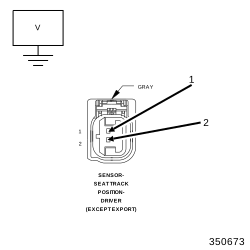
6. CHECK (R261) DRIVER SEAT POSITION SENSOR SIGNAL CIRCUIT AND (R263) DRIVER SEAT POSITION SENSOR SUPPLY CIRCUIT FOR A SHORT TO VOLTAGE
 |
Turn the ignition off, disconnect
the 12-volt battery and wait two minutes before proceeding. Failure
to follow these instructions may result in possible serious or fatal
injury.
WARNING:
| 1. | Disconnect the ORC connectors. |
Turn the ignition on, then reconnect
the 12-volt battery and wait two minutes before proceeding. Failure
to follow these instructions may result in possible serious or fatal
injury.
WARNING:
| 2. | Measure the voltage of the (R261) Driver Seat Position Sensor Signal circuit between the Driver Seat Track Position Sensor connector and ground. |
| 3. | Measure the voltage of the (R263) Driver Seat Position Sensor Supply circuit between the Driver Seat Track Position Sensor connector and ground. |
Is the voltage above 0.2 of a volt on either circuit?
Yes
-
NOTE: Do not attempt to repair the Seat Harness. Replace the Seat Harness if any of these conditions exist -
WARNING: Turn the ignition off, disconnect the 12-volt battery and wait two minutes before proceeding. Failure to follow these instructions may result in possible serious or fatal injury.
- Replace the Driver Seat Harness in accordance with the Service Information.
- Perform the AIRBAG SYSTEM VERIFICATION TEST. (Refer to 28 - DTC-Based Diagnostics/CONTROLLER, Occupant Restraint (ORC) - Standard Procedure).
No
-
Go To 7
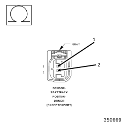
7. CHECK (R261) DRIVER SEAT POSITION SENSOR SIGNAL CIRCUIT FOR A SHORT TO (R263) DRIVER SEAT POSITION SENSOR SUPPLY CIRCUIT
 |
Turn the ignition off, disconnect
the 12-volt battery and wait two minutes before proceeding. Failure
to follow these instructions may result in possible serious or fatal
injury.
WARNING:
| 1. | Measure the resistance between the (R261) Driver Seat Position Sensor Signal circuit and the (R263) Driver Seat Position Sensor Supply circuit in the Driver Seat Track Position Sensor connector. |
Is the resistance below 10k Ohms?
Yes
-
NOTE: Do not attempt to repair the Seat Harness. Replace the Seat Harness if any of these conditions exist - Replace the Driver Seat Harness in accordance with the service information.
- Perform the AIRBAG SYSTEM VERIFICATION TEST. (Refer to 28 - DTC-Based Diagnostics/CONTROLLER, Occupant Restraint (ORC) - Standard Procedure).
No
-
WARNING: If the Occupant Restraint Controller (ORC) is dropped at any time, it must be replaced. Failure to follow these instructions may result in possible serious or fatal injury.
- Replace the ORC in accordance with the Service information.
-
Perform the AIRBAG SYSTEM VERIFICATION TEST. (Refer to 28 - DTC-Based Diagnostics/CONTROLLER, Occupant Restraint (ORC)
- Standard Procedure).
8. TEST FOR AN INTERMITTENT CONDITION
| 1. | With the scan tool, record and erase all DTC from the ORC. |
| 2. | If any ACTIVE codes are present they must be resolved before diagnosing any stored codes. |
Turn the ignition off, disconnect
the 12-volt battery and wait two minutes before proceeding. Failure
to follow these instructions may result in possible serious or fatal
injury.
WARNING:
| 3. | Using the wiring diagram/schematic as a guide, inspect the wiring and connectors. |
| 4. | Look for chafed, pierced, pinched, or partially broken wires and broken, bent, pushed out, spread, corroded, or contaminated terminals. |
| 5. | The following additional checks may assist you in identifying a possible intermittent problem. |
| 6. | Reconnect any disconnected components and harness connector. |
Turn the ignition on, then reconnect
the 12-volt battery and wait two minutes before proceeding. Failure
to follow these instructions may result in possible serious or fatal
injury.
WARNING:
| 7. | With the scan tool monitor active codes as you work through the following steps. |
Maintain a safe distance from all
airbags while performing the following steps. Failure to follow these
instructions may result in possible serious or fatal injury.
WARNING:
| 8. | Wiggle the wiring harness and connectors of the related airbag circuit or component. |
| 9. | If only stored codes return continue the test until the problem area has been isolated. |
| 10. | In the previous steps you have attempted to recreate the conditions responsible for setting active DTC in question. |
Are any ACTIVE DTC present?
Yes
- (Refer to 28 - DTC-Based Diagnostics/CONTROLLER, Occupant Restraint (ORC) - Diagnosis and Testing) and perform the appropriate diagnostic procedure.
No