2012 Jeep Wrangler JK Factory Service Manual 28 - DTC-Based Diagnostics

C1082-VACUUM PRESSURE SENSOR CIRCUIT

C1082-VACUUM PRESSURE SENSOR CIRCUIT


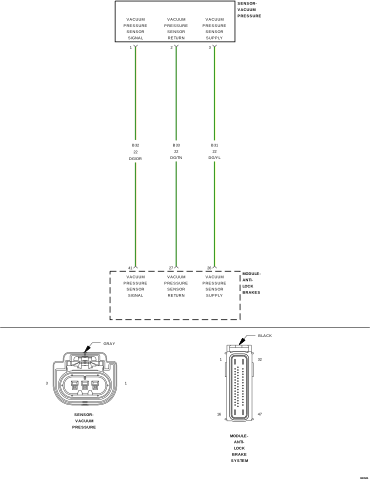
For a complete wiring diagram, refer to the Wiring Information.


Possible Causes

(B31) VACUUM PRESSURE SENSOR SUPPLY CIRCUIT OPEN OR HIGH RESISTANCE
(B32) VACUUM PRESSURE SENSOR SIGNAL CIRCUIT SHORTED TO VOLTAGE
(B32) VACUUM PRESSURE SENSOR SIGNAL CIRCUIT SHORTED TO GROUND
(B32) VACUUM PRESSURE SENSOR SIGNAL CIRCUIT OPEN OR HIGH RESISTANCE
(B33) VACUUM PRESSURE SENSOR RETURN CIRCUIT OPEN OR HIGH RESISTANCE
VACUUM PRESSURE SENSOR
ANTI-LOCK BRAKE SYSTEM (ABS) MODULE

1. VERIFY THE DTC IS ACTIVE


1. Perform any Technical Service Bulletins (TSBs) that may apply.
2. Ignition on, engine not running.
3. With the scan tool, record and erase the DTCs.
4. Cycle the ignition switch from off to on.
5. With the scan tool, read the DTCs.


Is the DTC active at this time?

Yes


No


2. (B31) VACUUM PRESSURE SENSOR SUPPLY CIRCUIT OPEN OR HIGH RESISTANCE


1. Turn ignition off to the lock position.
2. Disconnect the ABS Module harness connector.
3. Measure the resistance of the (B31) Vacuum Pressure Sensor Supply circuit between the Vacuum Pressure Sensor harness connector and the ABS Module harness connector.

Is the resistance below 5.0 Ohms?

Yes


No


3. (B32) VACUUM PRESSURE SENSOR SIGNAL CIRCUIT SHORTED TO VOLTAGE


1. Turn ignition off to the lock position.
2. Disconnect the ABS Module harness connector.
3. Disconnect the Vacuum Pressure Sensor harness connector.
4. Ignition on, engine not running.
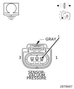
5. Measure the voltage between ground and the (B32) Vacuum Pressure Sensor Signal circuit at the Vacuum Pressure Sensor harness connector.


Is there any voltage present?

Yes


No


4. (B32) VACUUM PRESSURE SENSOR SIGNAL CIRCUIT SHORTED TO GROUND


1. Turn ignition off to the lock position.
2. Disconnect the ABS Module harness connector.
3. Measure the resistance between ground and the (B32) Vacuum Pressure Sensor Signal circuit at the Vacuum Pressure Sensor harness connector.


Is the resistance below 5.0 Ohms?

Yes


No


5. (B32) VACUUM PRESSURE SENSOR SIGNAL CIRCUIT OPEN OR HIGH RESISTANCE


1. Turn ignition off to the lock position.
2. Disconnect the ABS Module harness connector.
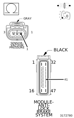
3. Measure the resistance of the (B32) Vacuum Pressure Sensor Signal circuit between the Vacuum Pressure Sensor harness connector and the ABS Module harness connector.
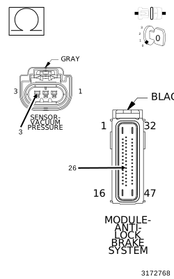

Is the resistance below 5.0 Ohms?

Yes


No


6. (B33) VACUUM PRESSURE SENSOR RETURN CIRCUIT OPEN OR HIGH RESISTANCE


1. Turn ignition off to the lock position.
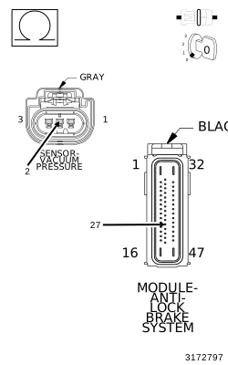
2. Measure the resistance of the (B33) Vacuum Pressure Sensor Return circuit between the Vacuum Pressure Sensor harness connector and the ABS Module harness connector.
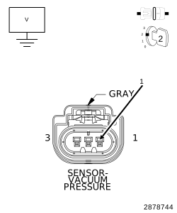

Is the resistance below 5.0 Ohms?

Yes


No


7. ANTI-LOCK BRAKE SYSTEM (ABS) MODULE


1. Turn the ignition off to the lock position.
2. Replace the Vacuum Pressure Sensor.
3. Perform the ABS VERIFICATION TEST. (Refer to 28 - DTC-Based Diagnostics/MODULE, Antilock Brake (ABS) - Standard Procedure).
4. With the scan tool, read the DTCs.


Is the DTC still active?

Yes


No