C1085-VACUUM PRESSURE SENSOR HIGH
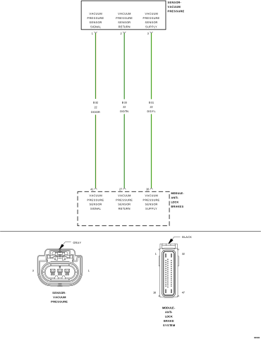
For a complete wiring diagram, refer to the Wiring Information.
-
When Monitored:
Continuous
-
Set Condition:
The Vacuum Sensor Signal indicates that the voltage level is below 0.1 volt or greater than 3.5 volts for 100 msec.
Possible Causes |
|---|
| (B32) VACUUM PRESSURE SENSOR SIGNAL CIRCUIT SHORTED TO VOLTAGE |
| (B32) VACUUM PRESSURE SENSOR SIGNAL CIRCUIT OPEN OR HIGH RESISTANCE |
| (B33) VACUUM PRESSURE SENSOR RETURN CIRCUIT OPEN OR HIGH RESISTANCE |
| VACUUM PRESSURE SENSOR |
| ANTI-LOCK BRAKE SYSTEM (ABS) MODULE |
| 1. | Perform any Technical Service Bulletins (TSBs) that may apply. |
| 2. | Ignition on, engine not running. |
| 3. | With the scan tool, record and erase the DTCs. |
| 4. | Cycle the ignition switch from off to on. |
| 5. | With the scan tool, read the DTCs. |
Is the DTC active at this time?
Yes
- Go To 2
No
- The condition that caused the symptom is currently not present. Inspect the related wiring for a possible intermittent condition. Look for any chafed, pierced, pinched, or partially broken wires.
- Perform the ABS-INTERMITTENT CONDITION TEST. (Refer to 28 - DTC-Based Diagnostics/MODULE, Antilock Brake (ABS) - Standard Procedure).
2. (B31) VACUUM PRESSURE SENSOR SUPPLY CIRCUIT OPEN OR HIGH RESISTANCE
| 1. | Turn ignition off to the lock position. |
| 2. | Disconnect the ABS Module harness connector. |
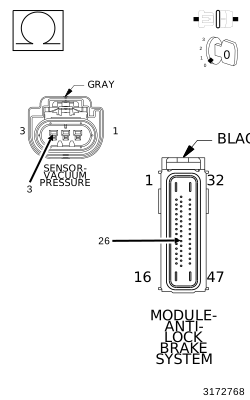
| 3. | Measure the resistance of the (B31) Vacuum Pressure Sensor Supply circuit between the Vacuum Pressure Sensor harness connector and the ABS Module harness connector. |
Is the resistance below 5.0 Ohms?
Yes
- Go To 3
No
- Repair the (B31) Vacuum Pressure Sensor Supply circuit for an open or high resistance.
-
Perform the ABS VERIFICATION
TEST. (Refer to 28 - DTC-Based
Diagnostics/MODULE, Antilock Brake (ABS)
- Standard Procedure).
3. (B32) VACUUM PRESSURE SENSOR SIGNAL CIRCUIT SHORTED TO VOLTAGE
| 1. | Turn ignition off to the lock position. |
| 2. | Disconnect the ABS Module harness connector. |
| 3. | Disconnect the Vacuum Pressure Sensor harness connector. |
| 4. | Ignition on, engine not running. |
| 5. | Measure the voltage between ground and the (B32) Vacuum Pressure Sensor Signal circuit at the Vacuum Pressure Sensor harness connector. |
Is there any voltage present?
Yes
- Repair the (B32) Vacuum Pressure Sensor Signal circuit for a short to ground.
- Perform the ABS VERIFICATION TEST. (Refer to 28 - DTC-Based Diagnostics/MODULE, Antilock Brake (ABS) - Standard Procedure).
No
-
Go To 4
4. (B32) VACUUM PRESSURE SENSOR SIGNAL CIRCUIT OPEN OR HIGH RESISTANCE
| 1. | Turn ignition off to the lock position. |
| 2. | Disconnect the ABS Module harness connector. |
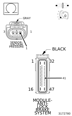
| 3. | Measure the resistance of the (B32) Vacuum Pressure Sensor Signal circuit between the Vacuum Pressure Sensor harness connector and the ABS Module harness connector. |
Is the resistance below 5.0 Ohms?
Yes
- Go To 5
No
- Repair the (B32) Vacuum Pressure Sensor Signal circuit for an open or high resistance.
-
Perform the ABS VERIFICATION
TEST. (Refer to 28 - DTC-Based
Diagnostics/MODULE, Antilock Brake (ABS)
- Standard Procedure).
5. (B33) VACUUM PRESSURE SENSOR RETURN CIRCUIT OPEN OR HIGH RESISTANCE
| 1. | Turn ignition off to the lock position. |
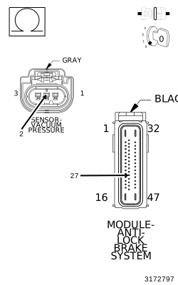
| 2. | Measure the resistance of the (B33) Vacuum Pressure Sensor Return circuit between the Vacuum Pressure Sensor harness connector and the ABS Module harness connector. |
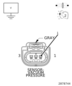
Is the resistance below 5.0 Ohms?
Yes
- Go To 6
No
- Repair the (B33) Vacuum Pressure Sensor Return circuit for an open or high resistance.
-
Perform the ABS VERIFICATION
TEST. (Refer to 28 - DTC-Based
Diagnostics/MODULE, Antilock Brake (ABS)
- Standard Procedure).
6. ANTI-LOCK BRAKE SYSTEM (ABS) MODULE
| 1. | Turn the ignition off to the lock position. |
| 2. | Replace the Vacuum Pressure Sensor. |
| 3. | Perform the ABS VERIFICATION TEST. (Refer to 28 - DTC-Based Diagnostics/MODULE, Antilock Brake (ABS) - Standard Procedure). |
| 4. | With the scan tool, read the DTCs. |
Is the DTC still active?
Yes
- Replace the Anti-lock Brake System (ABS) Module in accordance with the Service Information. (Refer to 08 - Electrical/8E - Electronic Control Modules/MODULE, Anti-Lock Brake System - Removal) .
- Perform the ABS VERIFICATION TEST. (Refer to 28 - DTC-Based Diagnostics/MODULE, Antilock Brake (ABS) - Standard Procedure).
No