U0125-LOST COMMUNICATION WITH DYNAMICS SENSOR
U0125-LOST COMMUNICATION WITH DYNAMICS SENSOR
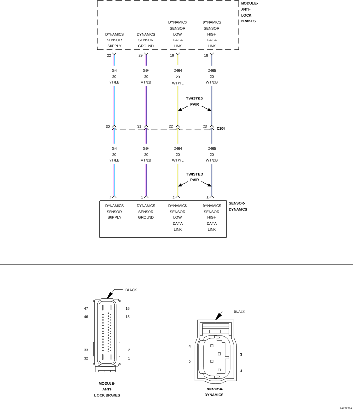 |
For a complete wiring diagram, refer to the Wiring Information.
-
When Monitored:
With the ignition on.
-
Set Condition:
If the Anti-Lock Brakes Module fails to receive bus messages from the Dynamics Sensor.
Possible Causes |
|---|
| WIRING HARNESS, TERMINAL, CONNECTOR DAMAGE |
| (G4) DYNAMICS SENSOR SUPPLY CIRCUIT SHORTED TO VOLTAGE, GROUND, OR OPEN |
| (G94) DYNAMICS SENSOR GROUND CIRCUIT SHORTED TO VOLTAGE, GROUND, OR OPEN |
| (D465) DYNAMICS SENSOR HIGH DATA LINK CIRCUIT SHORTED TO GROUND, SHORTED TO VOLTAGE, OR OPEN |
| (D464) DYNAMICS SENSOR LOW DATA LINK CIRCUIT SHORTED TO GROUND, SHORTED TO VOLTAGE, OR OPEN |
| DYNAMICS SENSOR |
| ANTI-LOCK BRAKE MODULE |
| NOTE: | If present, diagnose and repair DTC C2114-DYNAMICS SENSOR SUPPLY VOLTAGE LOW or DTC C2115–DYNAMICS SENSOR SUPPLY VOLTAGE HIGH before proceeding. |
| 1. | Turn the ignition on. |
| 2. | With the scan tool, read and record ABS DTCs. |
| 3. | With the scan tool, read and record Environmental Data to help identify the conditions in which the DTC was set. |
| 4. | With the scan tool, erase ABS DTCs. |
| 5. | Start the engine. |
| NOTE: | Attempt to operate the vehicle under conditions similar to which the DTC was set. It may be necessary to test drive the vehicle within the DTC monitoring and set conditions in order for this DTC to set. |
| 6. | With the scan tool, read ABS DTCs. |
Does this DTC reset?
Yes
- Go To 2
No
- The condition that caused the symptom is currently not present. Inspect the related wiring for a possible intermittent condition. Look for any chafed, pierced, pinched, or partially broken wires.
-
Perform the ABS INTERMITTENT CONDITION TEST (Refer to 28 - DTC-Based Diagnostics/MODULE, Antilock Brake (ABS)
- Standard Procedure).
2. INSPECT RELATED WIRING HARNESS, TERMINALS, AND CONNECTORS
| 1. | Visually inspect the related wiring harness. Look for any pinched, chafed, pierced, and partially broken wires. |
| 2. | Visually inspect the related wiring harness connectors. Look for broken, bent, pushed out, and corroded terminals. |
Were any problems found?
Yes
- Repair as necessary.
- Perform ABS VERIFICATION TEST (Refer to 28 - DTC-Based Diagnostics/MODULE, Antilock Brake (ABS) - Standard Procedure).
No
-
Go To 3
3. CHECK THE VOLTAGE ON THE (G4) DYNAMICS SENSOR SUPPLY CIRCUIT
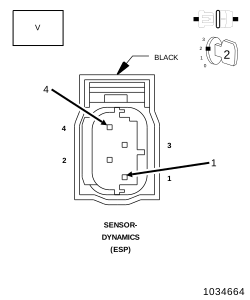 |
| 1. | Turn the ignition off. |
| 2. | Disconnect the Dynamics Sensor harness connector. |
| 3. | Turn the ignition on. |
| 4. | Measure the voltage across (G4) Dynamics Sensor Supply Circuit and (G94) Dynamics Sensor Ground Circuit. |
Is the voltage above 10 volts?
Yes
- Go To 10
No
-
Go To 4
4. (G4) DYNAMICS SENSOR SUPPLY CIRCUIT SHORT TO GROUND
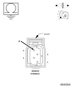 |
| 1. | Turn the ignition off. |
| 2. | Disconnect the Anti-Lock Brake Module harness connector. |
| 3. | Measure the resistance between ground and the (G4) Dynamics Sensor Supply circuit. |
Is the resistance below 5.0 ohms?
Yes
- Repair the (G4) Dynamics Sensor Supply circuit for a short to ground.
- Perform ABS VERIFICATION TEST (Refer to 28 - DTC-Based Diagnostics/MODULE, Antilock Brake (ABS) - Standard Procedure).
No
-
Go To 5
5. (G4) DYNAMICS SENSOR SUPPLY CIRCUIT SHORT TO VOLTAGE
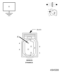 |
| 1. | Turn the ignition on. |
| 2. | Measure the voltage of the (G4) Dynamics Sensor Supply circuit. |
Is there any voltage present?
Yes
- Repair the (G4) Dynamics Sensor Supply circuit for a short to voltage.
- Perform ABS VERIFICATION TEST (Refer to 28 - DTC-Based Diagnostics/MODULE, Antilock Brake (ABS) - Standard Procedure).
No
-
Go To 6
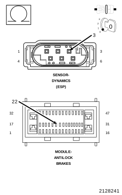
6. (G4) DYNAMICS SENSOR SUPPLY CIRCUIT OPEN
 |
| 1. | Turn the ignition off. |
| 2. | Measure the resistance of the (G4) Dynamics Sensor Supply circuit. |
Is the resistance below 5.0 ohms?
Yes
- Go To 7
No
- Repair the (G4) Dynamics Sensor Supply circuit for an open.
-
Perform ABS VERIFICATION TEST (Refer to 28 - DTC-Based Diagnostics/MODULE, Antilock Brake (ABS)
- Standard Procedure).
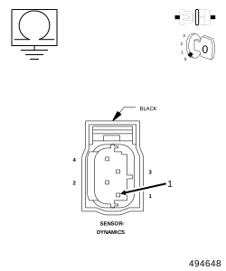
7. CHECK THE RESISTANCE BETWEEN THE (G94) DYNAMICS SENSOR GROUND CIRCUIT AND GROUND
 |
| 1. | Disconnect the Dynamics Sensor harness connector. |
| 2. | Measure the resistance between the (G94) Dynamics Sensor Ground Circuit and Ground. |
Is the resistance below 5.0 ohm?
Yes
- Replace the Anti-Lock Brake Module in accordance with the Service Information.
- Perform ABS VERIFICATION TEST (Refer to 28 - DTC-Based Diagnostics/MODULE, Antilock Brake (ABS) - Standard Procedure).
No
-
Go To 8
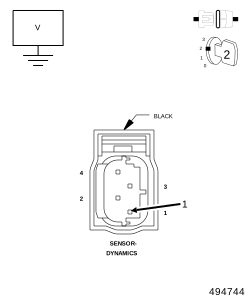
8. (G94) DYNAMICS SENSOR GROUND CIRCUIT SHORT TO VOLTAGE
 |
| 1. | Turn the ignition off. |
| 2. | Disconnect the Anti-Lock Brake Module harness connector. |
| 3. | Turn the ignition on. |
| 4. | Measure the voltage of the (G94) Dynamics Sensor Ground circuit. |
Is there any voltage present?
Yes
- Repair the (G94) Dynamics Sensor Ground circuit for a short to voltage.
- Perform ABS VERIFICATION TEST (Refer to 28 - DTC-Based Diagnostics/MODULE, Antilock Brake (ABS) - Standard Procedure).
No
-
Go To 9
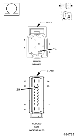
9. (G94) DYNAMICS SENSOR GROUND CIRCUIT OPEN
 |
| 1. | Turn the ignition off. |
| 2. | Measure the resistance of the (G94) Dynamics Sensor Return circuit between the Dynamics Sensor and the Anti-Lock Brake Module. |
Is the resistance below 5.0 ohms?
Yes
- Replace the Anti-Lock Brake Module in accordance with the Service Information.
- Perform ABS VERIFICATION TEST (Refer to 28 - DTC-Based Diagnostics/MODULE, Antilock Brake (ABS) - Standard Procedure).
No
- Repair the (G94) Dynamics Sensor Ground circuit for an open.
-
Perform ABS VERIFICATION TEST (Refer to 28 - DTC-Based Diagnostics/MODULE, Antilock Brake (ABS)
- Standard Procedure).
10. CHECK THE DATA LINK OUTPUT
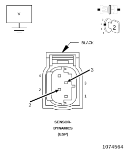 |
| 1. | Measure the voltage of the Data Links Circuits the (D465) DYNAMICS SENSOR HIGH DATA LINK CIRCUIT will measure a minimum of 3 volts and the (D464) DYNAMICS SENSOR LOW DATA LINK CIRCUIT will measure a minimum of 2 volts |
Is the voltage within specifications?
Yes
- Replace the Dynamic Sensor in accordance with the Service Information.
- Perform ABS VERIFICATION TEST (Refer to 28 - DTC-Based Diagnostics/MODULE, Antilock Brake (ABS) - Standard Procedure).
No
-
Go To 11
11. CHECK THE (D465) DYNAMICS SENSOR HIGH DATA LINK CIRCUIT FOR A SHORT TO VOLTAGE
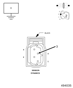 |
| 1. | Disconnect the Anti-Lock Brakes Module harness connector. |
| 2. | Disconnect the Dynamics Sensor harness connector. |
| 3. | Turn the ignition on. |
| 4. | Measure the voltage of the (D465) Dynamics Sensor High Data Link circuit. |
Is there any voltage present?
Yes
- Repair the (D465) Dynamics Sensor High Data Link circuit for a short to voltage.
- Perform ABS VERIFICATION TEST (Refer to 28 - DTC-Based Diagnostics/MODULE, Antilock Brake (ABS) - Standard Procedure).
No
-
Go To 12
12. CHECK THE (D465) DYNAMICS SENSOR HIGH DATA LINK CIRCUIT FOR A SHORT TO GROUND
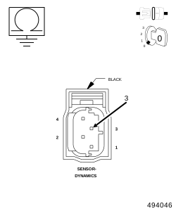 |
| 1. | Turn the ignition off. |
| 2. | Measure the resistance of the (D465) Dynamics Sensor High Data Link circuit between ground and the Dynamics Sensor harness connector. |
Is the resistance below 5.0 ohms?
Yes
- Repair the (D465) Dynamics Sensor High Data Link circuit for a short to ground.
- Perform ABS VERIFICATION TEST (Refer to 28 - DTC-Based Diagnostics/MODULE, Antilock Brake (ABS) - Standard Procedure).
No
-
Go To 13
13. CHECK THE (D465) DYNAMICS SENSOR HIGH DATA LINK CIRCUIT FOR AN OPEN
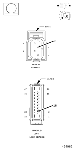 |
| 1. | Measure the resistance of the (D465) Dynamics Sensor High Data Link circuit between the Dynamics Sensor harness connector and the Anti-Lock Brakes Module harness connector. |
Is the resistance below 5.0 ohms?
Yes
- Go To 14
No
- Repair the (D465) Dynamics Sensor High Data Link circuit for an open.
-
Perform ABS VERIFICATION TEST (Refer to 28 - DTC-Based Diagnostics/MODULE, Antilock Brake (ABS)
- Standard Procedure).
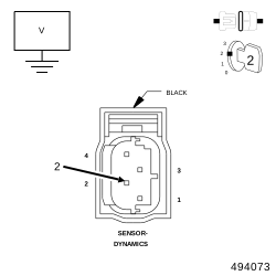
14. CHECK THE (D464) DYNAMICS SENSOR LOW DATA LINK CIRCUIT FOR A SHORT TO VOLTAGE
 |
| 1. | Turn the ignition on. |
| 2. | Measure the voltage of the (D464) Dynamics Sensor Low Data Link circuit. |
Is there any voltage present?
Yes
- Repair the (D464) Dynamics Sensor Low Data Link circuit for a short to voltage.
- Perform ABS VERIFICATION TEST (Refer to 28 - DTC-Based Diagnostics/MODULE, Antilock Brake (ABS) - Standard Procedure).
No
-
Go To 15
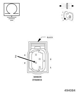
15. CHECK THE (D464) DYNAMICS SENSOR LOW DATA LINK CIRCUIT FOR A SHORT TO GROUND
 |
| 1. | Turn the ignition off. |
| 2. | Measure the resistance of the (D464) Dynamics Sensor Low Data Link circuit between ground and the Dynamics Sensor harness connector. |
Is the resistance below 5.0 ohms?
Yes
- Repair the (D464) Dynamics Sensor Low Data Link circuit for a short to ground.
- Perform ABS VERIFICATION TEST (Refer to 28 - DTC-Based Diagnostics/MODULE, Antilock Brake (ABS) - Standard Procedure).
No
-
Go To 16
16. CHECK THE (D464) DYNAMICS SENSOR LOW DATA LINK CIRCUIT FOR AN OPEN
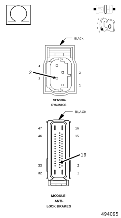 |
| 1. | Measure the resistance of the (D464) Dynamics Sensor Low Data Link circuit between the Dynamics Sensor harness connector and the Anti-Lock Brake Module harness connector. |
Is the resistance below 5.0 ohms?
Yes
- Replace the Anti-Lock Brake Module in accordance with the Service Information.
- Perform ABS VERIFICATION TEST (Refer to 28 - DTC-Based Diagnostics/MODULE, Antilock Brake (ABS) - Standard Procedure).
No
- Repair the (D464) Dynamics Sensor Low Data Link circuit for an open.
-
Perform ABS VERIFICATION TEST (Refer to 28 - DTC-Based Diagnostics/MODULE, Antilock Brake (ABS)
- Standard Procedure).