U0126-LOST COMMUNICATION WITH STEERING ANGLE SENSOR
For a complete wiring diagram, refer to the Wiring Information.
| NOTE: |
The Electronic Stability Control (ESC) may also be referred to as Electronic Stability Program (ESP) depending on the vehicle model year and configuration. Certain components may also reference ESP, ESC, or use the traction control symbol. |
- When Monitored:
-
Set Condition:
If the Anti-Lock Brake System (ABS) Module fails to receive bus messages from the Steering Angle Sensor for approximately 500 ms.
Possible Causes |
|---|
| DTCs RELATED TO BATTERY VOLTAGE, IGNITION, OR VIN MESSAGES |
| (F943) FUSED B(+) CIRCUIT OPEN OR HIGH RESISTANCE |
| (Z910) GROUND CIRCUIT OPEN OR HIGH RESISTANCE |
| CAN C BUS CIRCUITS OPEN OR SHORTED |
| CLOCKSPRING (SAS) |
| NOTE: | Make sure the IOD fuse is installed and battery voltage is between 10 and 16 volts before proceeding. |
| 1. | Turn the ignition on. |
| 2. | With the scan tool, read and record the ABS DTCs. |
| 3. | With the scan tool, read and record the Environmental Data to help identify the conditions in which the DTC was set. |
| 4. | With the scan tool, erase ABS DTCs. |
| 5. | Cycle the ignition switch. |
| 6. | With the scan tool, read the ABS DTCs. |
Does this DTC reset?
Yes
- Go To 2
No
- The condition that caused the symptom is currently not present. Inspect the related wiring for a possible intermittent condition. Look for any chafed, pierced, pinched or partially broken wires.
- Perform the ABS INTERMITTENT CONDITION TEST. (Refer to 28 - DTC-Based Diagnostics/MODULE, Antilock Brake (ABS) - Standard Procedure).
2. CHECK FOR ANY OF THE FOLLOWING ACTIVE DTCs
| 1. | With the scan tool, read all active DTCs from all CAN C Bus modules. |
| NOTE: | Check for CAN C hardware electrical, VIN Missing/Mismatch, battery or ignition related DTCs. |
Does the scan tool display any active DTCs related to the conditions listed above?
Yes
No
- Go To 3
3. CHECK THE (F943) FUSED B(+) CIRCUIT FOR AN OPEN OR HIGH RESISTANCE
| 1. | Turn the ignition off. |
| 2. | Disconnect the Clockspring C3 harness connector. |
| 3. | Turn the ignition on. |
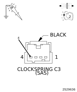
| 4. | Using a 12-volt test light connected to ground, check the (F943) Fused B(+) circuit at the Clockspring C3 harness connector. |
| NOTE: | The test light should be illuminated and bright. Compare the brightness to that of a direct connection to the battery. |
Does the test light illuminate brightly?
Yes
- Go To 4
No
- Repair the (F943) Fused Run/Start circuit for an open.
-
Perform the ABS VERIFICATION TEST. (Refer to 28 - DTC-Based Diagnostics/MODULE, Antilock Brake (ABS)
- Standard Procedure).
4. CHECK THE (Z910) GROUND CIRCUIT FOR AN OPEN OR HIGH RESISTANCE
| 1. | Turn the ignition off. |
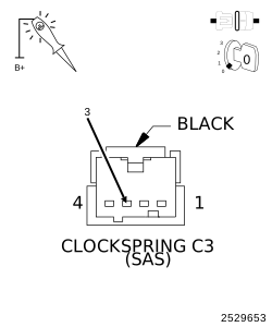
| 2. | With a 12-volt test light connected to B+, check the (Z910) Ground circuit at the Clockspring C3 harness connector. |
| NOTE: | The test light should be illuminated and bright. Compare the brightness to that of a direct connection to the battery. |
Does the test light illuminate brightly?
Yes
- Go To 5
No
- Repair the (Z910) Ground circuit for an open.
-
Perform the ABS VERIFICATION TEST. (Refer to 28 - DTC-Based Diagnostics/MODULE, Antilock Brake (ABS)
- Standard Procedure).
5. VERIFY THAT THE STEERING ANGLE SENSOR IS ACTIVE ON THE BUS
| 1. | With the scan tool, select ECU View. |
| 2. | Verify that the Steering Angle Sensor is active on the bus. |
Is the Steering Angle Sensor active on the bus?
Yes
- Replace the Clockspring in accordance with the Service Information.
- Perform the ABS VERIFICATION TEST. (Refer to 28 - DTC-Based Diagnostics/MODULE, Antilock Brake (ABS) - Standard Procedure).
No
- (Refer to 29 - Non-DTC Diagnostics/Communication - Diagnosis and Testing) and perform the Stored Loss of Communication diagnostic procedure.